 Skip to content
Struggling to choose the right material for your PCB design? The dielectric you pick affects everything from performance to cost, and making the wrong choice can lead to project failure.
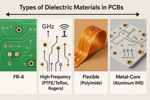
The main types of dielectric materials used in PCBs are FR-4 (epoxy resin and woven glass), high-frequency materials (like PTFE/Teflon and Rogers), flexible materials (like Polyimide), and metal-core substrates (like aluminum-backed IMS). The choice depends on thermal, electrical, and mechanical requirements.
Choosing the right dielectric is a critical decision in any hardware design. It's not just about electrical properties; it's about ensuring your product can be manufactured reliably and survive in its intended environment. I've seen projects get derailed by poor material choices, leading to costly redesigns and schedule delays. Let's explore these materials in depth, so you can make an informed decision for your next project.
What Is The Most Common Dielectric Material Used In PCBs?
Wondering what material forms the backbone of most electronics today? You see it everywhere, but its specific properties are what make it the industry's default choice for countless applications.
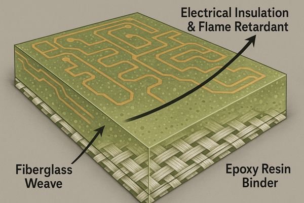
The most common dielectric material is FR-4. It's a composite of woven fiberglass cloth with an epoxy resin binder that is flame retardant (FR). Its balance of low cost, good electrical insulation, and excellent mechanical strength makes it suitable for a vast range of electronic products.
FR-4: The Industry's Workhorse Explained
When I first started in this industry, FR-4 seemed like just a generic green board. But its ubiquity is no accident. FR-4 hits the sweet spot between performance, manufacturability, and cost. It's the workhorse of the electronics world for a reason. Its full name, "Flame Retardant 41," tells you a key property: it self-extinguishes if it catches fire, a critical safety feature for most electronics.
The material's properties are defined by standards like IPC-41012, "Specification for Base Materials for Rigid and Multilayer Printed Boards." This standard provides "slash sheets" that specify material characteristics. For example, IPC-4101/21 describes a common standard-\(T_{g}\) FR-4. For lead-free soldering or hotter environments, we use high-\(T_{g}\) materials like those defined in IPC-4101/126, which specifies a \(T_{g} \geq 170\) °C. This higher thermal stability prevents the board from deforming or delaminating. This upgrade comes at a cost, but it's essential for reliability. Higher-grade FR-4 materials also offer better resistance to Conductive Anodic Filament (CAF)3 formation—where conductive filaments grow along the glass fibers in humid conditions, which can cause short circuits.
Here is a quick comparison of the common FR-4 grades:
| FR-4 Grade | Typical \(T_{g}\) Range | Typical \(T_{d}\) Range | Relative Cost | Common Use Case |
|---|---|---|---|---|
| Standard \(T_{g}\) (IPC-4101/21) | 130 - 140 °C | \(\approx\)300 °C | Base (1x) | Consumer electronics, simple circuits, cost-sensitive designs. |
| Mid \(T_{g}\) (IPC-4101/99) | 150 - 160 °C | \(\approx\)325 °C | \(\approx\)1.1x - 1.2x | Automotive, industrial controls, multilayer boards. |
| High \(T_{g}\) (IPC-4101/126) | \(\geq 170\) °C | \(\approx\)340 °C | \(\approx\)1.2x - 1.4x | Servers, telecom, lead-free assembly, high-reliability. |
What Is The Difference Between PCB Core And Prepreg?
Building a multilayer PCB and confused by the terms 'core' and 'prepreg'? Using them incorrectly can lead to manufacturing errors, so understanding their distinct roles is essential for every hardware engineer.
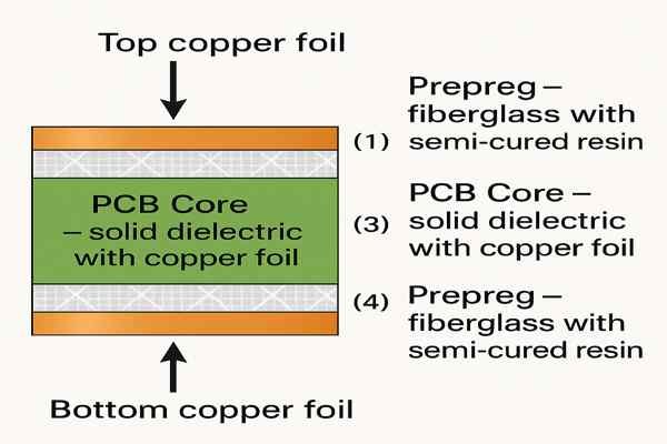
A PCB core is a rigid piece of dielectric material with copper foil laminated on one or both sides. Prepreg is a thin sheet of fiberglass impregnated with partially cured (B-stage) epoxy resin. Prepreg acts as the glue to bond cores and copper foils together during lamination.
The Building Blocks of a Multilayer PCB
Think of building a multilayer board like making a lasagna. The 'cores' are like the pasta sheets that already have sauce on them (the copper). The 'prepreg4' is the ricotta cheese and mozzarella you layer in between to bind everything together when you bake it. This "baking" is the lamination process, where heat and pressure are applied.
The prepreg starts in a partially cured "B-stage," meaning the epoxy is still thermoplastic and can be reformed. When heated past its glass transition temperature during lamination, it flows and fills any gaps around the copper traces. As it cools, it cross-links and becomes a fully cured "C-stage" thermoset plastic, just like the core material. This is an irreversible chemical change that permanently bonds the layers.
For a typical 4-layer PCB, the stack-up would be: Top Copper Foil -> Prepreg -> Core -> Prepreg -> Bottom Copper Foil. The type of glass weave in the prepreg is critical as it defines the final pressed thickness and affects impedance.
Here are some common prepreg styles you'll see on fabrication drawings:
| Weave Style | Typical Pressed Thickness | Resin Content | Weave Pattern | Typical Application |
|---|---|---|---|---|
| 106 | \(\approx\)2.1 mils (\(\approx\)53 µm) | High | Tight, fine | Thin dielectric layers, filling fine gaps, impedance control. |
| 1080 | \(\approx\)2.5 mils (\(\approx\)64 µm) | High | Tight | General purpose, controlled impedance on outer layers. |
| 2116 | \(\approx\)3.7 mils (\(\approx\)94 µm) | Medium | Medium | A good balance for building thickness and impedance control. |
| 7628 | \(\approx\)7.0 mils (\(\approx\)178 µm) | Low | Coarse, open | Building thick PCBs, power planes, not ideal for high speed. |
What Do Material Properties Like Dielectric Constant, Dissipation Factor, And Glass Transition Temperature Signify?
Are terms like \(D_{k}\), \(D_{f}\), and \(T_{g}\) just confusing datasheet jargon? These properties are fundamental to your PCB's performance, reliability, and manufacturability. Ignoring them can lead to signal degradation and field failures.
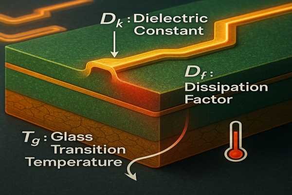
These properties define a material's electrical and thermal performance. The dielectric constant (\(D_{k}\)) affects signal speed and impedance. The dissipation factor (\(D_{f}\)) measures signal loss. The glass transition temperature (\(T_{g}\)) indicates the material's thermal stability, which is critical for both assembly and long-term reliability.
Key Performance Indicators for PCB Materials
Understanding these parameters is non-negotiable for serious hardware design. They directly influence whether your circuit will work as simulated. Let's break them down and add a couple more related thermal properties.
Dielectric Constant5 (\(D_{k}\) or \(\epsilon_{r}\))
The dielectric constant determines how fast an electrical signal travels and is key for trace impedance. A lower \(D_{k}\) means faster signals. Standard FR-4 has a \(D_{k}\) around 4.0 to 4.8. For high-speed designs, a material like Rogers RO4350B with a stable \(D_{k}\) of 3.48 is better. The inconsistency in FR-4 comes from its composite nature. The glass fibers have a \(D_{k} \approx 6\), while the epoxy resin is closer to \(D_{k} \approx 3\). This creates the "fiber weave effect," where a trace running parallel to the weave sees a different average \(D_{k}\) than one running diagonally. This can cause timing skew in multi-gigabit signals.
Dissipation Factor6 (\(D_{f}\) or \(\text{Tan}\delta\))
The dissipation factor, or loss tangent, measures how much signal energy is lost as heat in the dielectric. A lower \(D_{f}\) is better. Standard FR-4 has a high \(D_{f}\) of about 0.015 to 0.025. For signals above a few GHz, this loss is like trying to run through mud—it just kills the signal integrity. For a 10 Gbps signal, a low-loss material like Isola IS680 or Panasonic's Megtron 6, with a \(D_{f} < 0.005\), is often required.
Thermal Properties: \(T_{g}\), \(T_{d}\), and CTE
\(T_{g}\) (Glass Transition Temperature7) is where the material changes from rigid to rubbery. It's not a melting point. Above \(T_{g}\), the material expands much more rapidly. \(T_{d}\) (Decomposition Temperature) is the point of chemical breakdown, where the material is permanently damaged. You must stay well below this. CTE (Coefficient of Thermal Expansion8) measures how much the material expands with heat. The Z-axis CTE is most critical. Below \(T_{g}\), it might be 60 ppm/°C. Above \(T_{g}\), it can jump to over 300 ppm/°C. This rapid expansion in thickness puts immense stress on the copper barrels of plated-through vias, which can cause them to crack and create open circuits. This is why using a material with a high \(T_{g}\) (e.g., 170 °C) is vital for lead-free assembly, which can peak at 260 °C. It keeps the board in its stable, low-expansion state.
This table compares a standard material against a high-frequency one:
| Property | Standard FR-4 | High-Frequency (e.g., Rogers 4350B) | Significance |
|---|---|---|---|
| Dielectric Constant (\(D_{k}\)) | \(\approx\)4.0 - 4.8 @ 1 MHz | \(3.48 \pm 0.05\) @ 10 GHz | Affects impedance and signal speed. Stability over frequency is key. |
| Dissipation Factor (\(D_{f}\)) | \(\approx\)0.015 - 0.025 | \(\approx\)0.0037 @ 10 GHz | Measures signal loss in the dielectric. Critical for high-speed/RF. |
| Glass Transition (\(T_{g}\)) | 130 - 140 °C | \(>280\) °C | Point where material softens and CTE increases dramatically. |
| Decomposition Temp (\(T_{d}\)) | \(\approx\)300 - 340 °C | \(>390\) °C | Point of irreversible chemical damage. Defines max survival temperature. |
| Z-axis CTE (Below \(T_{g}\)) | \(\approx\)60 ppm/°C | \(\approx\)50 ppm/°C | Rate of expansion in thickness. Lower is better for via reliability. |
Conclusion
Choosing the right PCB dielectric is foundational. FR-4 is the workhorse, but high-frequency and high-temperature needs demand specialized materials. Understanding core, prepreg, \(D_{k}\), \(D_{f}\), and \(T_{g}\) is essential.
-
Explore the advantages of Flame Retardant 4, a crucial material in electronics, to understand its safety and performance benefits. ↩
-
Learn about IPC-4101, the standard that defines material properties for PCBs, ensuring quality and reliability in electronics. ↩
-
Discover the impact of Conductive Anodic Filament on electronic reliability and how to mitigate its risks in humid conditions. ↩
-
Understanding prepreg is crucial for grasping how multilayer PCBs are constructed and their performance characteristics. ↩
-
Understanding the Dielectric Constant is crucial for optimizing signal speed and integrity in PCB design. Explore this link to enhance your knowledge. ↩
-
The Dissipation Factor directly impacts signal loss and performance. Learn more about its significance in PCB materials to improve your designs. ↩
-
Understanding the Glass Transition Temperature is crucial for selecting materials that maintain stability under heat, especially in electronics. ↩
-
Exploring the Coefficient of Thermal Expansion helps in understanding how materials behave under temperature changes, impacting design and reliability. ↩


