 Skip to content
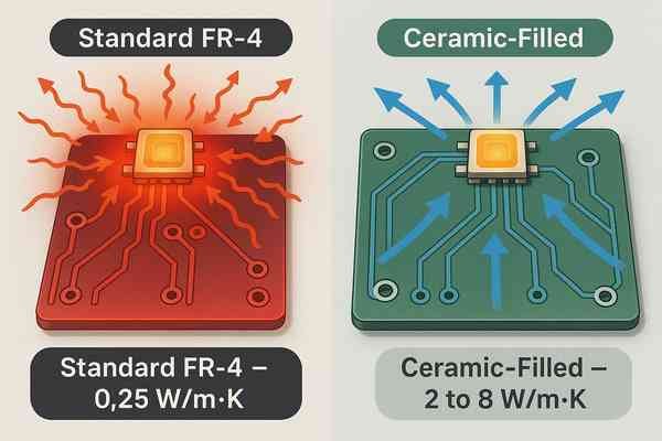
Your high-power components are overheating on standard FR-4. This thermal stress threatens your design's reliability, risking catastrophic failure. The solution lies in materials engineered for superior heat dissipation.
Ceramic-filled PCB materials are used for applications requiring superior thermal conductivity, often ranging from \(2 \text{ to } 8 \text{ W/m}\cdot\text{K}\), compared to just \(0.25 \text{ W/m}\cdot\text{K}\) for standard FR-4. They efficiently dissipate heat from high-power LEDs, RF amplifiers, and automotive electronics.
The Mechanics of Ceramic-Filled Laminates
When a design absolutely must get heat away from a component, ceramic-filled laminates are a game-changer. These aren't fully ceramic boards, which are a different technology (like Direct Bonded Copper). Instead, these are polymer-based laminates, like epoxy, filled with thermally conductive ceramic powders. The type of ceramic filler dictates performance and cost.
| Filler Material | Thermal Conductivity (\(\text{W/m}\cdot\text{K}\)) | Relative Cost | Key Application |
|---|---|---|---|
| Alumina (\(Al_{2}O_{3}\)) | \(1 - 3\) | Low | General purpose, LEDs, Power Supplies |
| Aluminum Nitride (\(AlN\)) | \(5 - 9\) | High | High-power RF, Automotive, Motor Drives |
| Boron Nitride (\(BN\)) | \(3 - 8\) | Very High | Extreme performance, Aerospace, Telecom |
The primary goal is to lower the thermal resistance1 between a hot component and a heatsink or metal core. By efficiently transferring heat, these materials keep component junction temperatures low, which directly improves reliability. I used a material from the Bergquist Thermal Clad series on a motor drive project, and it allowed us to shrink the overall product size by eliminating the need for a bulky, fan-cooled heatsink. However, be aware that these materials can be more abrasive, requiring specialized tooling for drilling and routing during fabrication.
What Materials Are Utilized for Flexible PCBs?
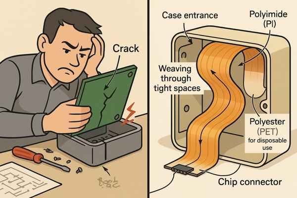
Trying to fit a rigid PCB into a compact product? It’s a frustrating puzzle that compromises your device's form factor and risks mechanical failure. Flexible PCBs provide the design freedom you need.
Flexible PCBs primarily use Polyimide (PI) as the base material due to its excellent thermal stability and mechanical durability. For lower-cost, disposable applications, Polyester (PET) is a common alternative.
A Closer Look at Flex Materials
When I design a product that needs to bend, like the interconnect in a laptop hinge or a sensor for a medical device, flexible PCBs are essential. The material choice is critical, and the design rules, governed by standards like IPC-2223, are different from rigid boards. A key parameter is the minimum bend radius. For a dynamic application (where the circuit flexes repeatedly), a good rule of thumb is to maintain a bend radius of at least \(10\times\) the circuit's thickness to prevent metal fatigue.
| Feature | Polyimide (PI)2 - e.g., Kapton® | Polyester (PET) |
|---|---|---|
| Max Process Temp. | \(\approx 260^{\circ}\text{C}\) (for lead-free soldering) | \(< 100^{\circ}\text{C}\) (not solderable) |
| Cost | Higher | Lower |
| Flexibility | Excellent (high cycle life) | Good (lower cycle life) |
| Primary Use | High-reliability, complex designs | Low-cost, membrane switches |
Beyond the base material, the adhesive system is also critical. While acrylic and epoxy adhesives are common, high-reliability designs often use "adhesiveless" base materials, where copper is deposited directly onto the polyimide. This eliminates the adhesive layer, which can be a weak point for delamination and moisture absorption.
What Are High-Tg PCB Materials and When Are They Necessary?
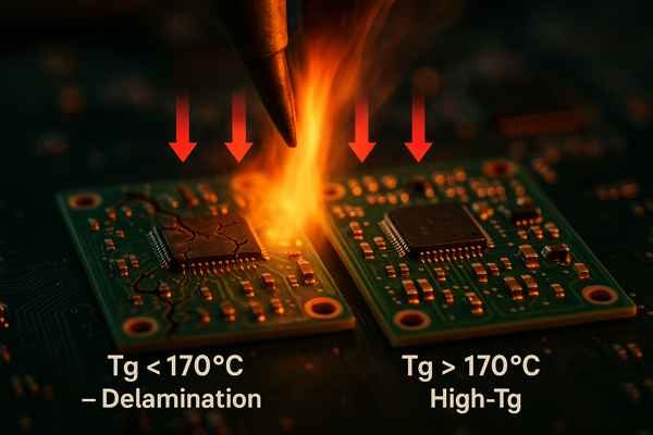
Worried about your boards failing during lead-free soldering? That intense heat can cause delamination and ruin entire production runs. High-Tg materials are the key to surviving modern assembly processes.
High-Tg materials are PCBs with a high glass transition temperature (\(T_{g}\)), typically \(> 170^{\circ}\text{C}\). They are necessary for lead-free assembly, high operating temperatures, or any design subject to significant thermal stress.
When to Specify a High-Tg Laminate
The glass transition temperature, or \(T_{g}\), is when a material transitions from a rigid solid to a softer state. While important, an even more critical parameter is the Decomposition Temperature (\(T_{d}\)). This is the temperature at which the material irreversibly degrades. A good high-Tg material provides a healthy margin for both.
| Parameter | Standard FR-4 | High-Tg Material (e.g., Isola 370HR) |
|---|---|---|
| Glass Transition Temp (\(T_{g}\)) | \(130^{\circ}\text{C} - 140^{\circ}\text{C}\) | \(> 170^{\circ}\text{C}\) |
| Decomposition Temp (\(T_{d}\)) | \(\approx 300^{\circ}\text{C}\) | \(> 340^{\circ}\text{C}\) |
| Z-Axis CTE (Below \(T_{g}\)) | \(\approx 60 \text{ ppm}/^{\circ}\text{C}\) | \(\approx 45 \text{ ppm}/^{\circ}\text{C}\) |
| Lead-Free Assembly | Risky | Recommended |
| Relative Cost | Baseline (\(1\times\)) | \(1.2\times - 1.5\times\) |
Here’s when you must specify a high-Tg laminate:
- Lead-Free Soldering: Lead-free processes require peak temperatures of \(240-260^{\circ}\text{C}\). A standard FR-4 board (\(T_{g} \approx 140^{\circ}\text{C}\)) is well into its soft state at these temperatures.
- High Thermal Loads: For automotive or industrial boards operating continuously at high temperatures.
- Improved Reliability: High-Tg materials have a lower Z-axis \(CTE\), putting less stress on plated-through-hole barrels and improving via reliability. For any board with more than 6 layers or expensive BGAs, I consider high-Tg a mandatory insurance policy.
What Is the Optimal Dielectric Material for RF and Microwave Circuits?
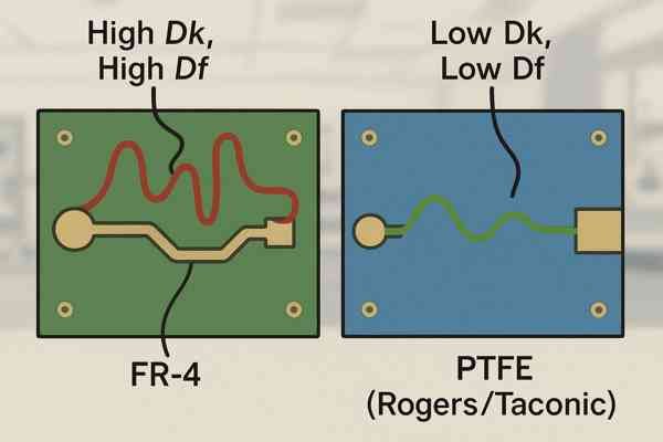
Are your RF circuits underperforming on standard FR-4? Signal loss and impedance shifts are killing your performance, making the design unreliable. Choosing the right low-loss dielectric is essential for predictable results.
The optimal dielectric material for RF circuits has a low, stable dielectric constant (\(D_{k}\)) and a low dissipation factor (\(D_{f}\)). PTFE-based materials (e.g., Rogers, Taconic) are ideal, while hydrocarbon ceramics (e.g., Rogers RO4000 series) offer a good performance/cost balance.
Key Properties of RF Dielectrics
For RF frequencies, success depends on two parameters: the dielectric constant3 (\(D_{k}\)) and the dissipation factor4 (\(D_{f}\)). The stability of \(D_{k}\) across frequency and temperature is critical; any variation will detune sensitive circuits like filters and matching networks. The low \(D_{f}\) ensures that signal power isn't lost as heat in the substrate.
| Material | Typical \(D_{k}\) (at \(10 \text{ GHz}\)) | Typical \(D_{f}\) (at \(10 \text{ GHz}\)) | Use Case |
|---|---|---|---|
| FR-4 | \(\approx 4.5\) (variable) | \(\approx 0.020\) | Low-frequency, digital |
| Rogers RO4350B | \(3.48 \pm 0.05\) | \(0.0037\) | RF up to \(\approx 20 \text{ GHz}\), cost-effective |
| Rogers RT/duroid 5880 | \(2.20 \pm 0.02\) | \(0.0009\) | Microwave \(> 20 \text{ GHz}\), high-perf |
In practice, we often use hybrid stackups to manage cost. This involves using a thin layer of expensive RF material on the outer layers for the RF circuitry, and standard FR-4 for the inner power and signal layers. Furthermore, for millimeter-wave frequencies (\(>30 \text{ GHz}\)), even the copper surface roughness matters. Skin effect causes the current to flow only on the surface of the copper. A rougher surface increases the path length and the loss. Specifying very-low-profile (VLP) copper foil becomes necessary to minimize this loss.
What Are Halogen-Free PCB Materials and For What Reason Are They Used?
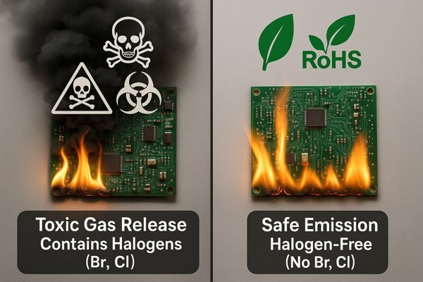
Do your product's materials pose a safety risk? In a fire, traditional PCBs can release toxic gases, creating a major compliance headache. Halogen-free laminates offer a safer, greener alternative.
Halogen-free PCB materials are substrates that do not contain bromine or chlorine flame retardants. They are used to comply with environmental standards (e.g., RoHS) and to enhance fire safety by preventing the release of toxic dioxin gas when burned.
Understanding Halogen-Free Standards and Trade-offs
The industry standard IEC 61249-2-21 defines "halogen-free" as containing less than \(900 \text{ ppm}\) of bromine or chlorine, and less than \(1500 \text{ ppm}\) of total halogens. Instead of halogenated compounds, these materials use phosphorus or nitrogen-based flame retardants. This is a requirement for many consumer products.
| Feature | Standard (Brominated) FR-4 | Halogen-Free Material |
|---|---|---|
| Flame Retardant | Bromine-based (TBBP-A) | Phosphorus or Nitrogen-based |
| Fire Byproducts | Toxic (Dioxins, Furans) | Less toxic smoke |
| Environmental | Contains persistent pollutants | "Greener" alternative |
| Moisture Absorption | Lower | Higher (may require baking) |
| Thermal Performance | Baseline \(T_{g}\) / \(CTE\) | Often higher \(T_{g}\) / lower \(CTE\) |
While the primary driver is safety, there are engineering trade-offs. Halogen-free resins tend to absorb more moisture, giving them a higher Moisture Sensitivity Level (MSL)5. This means they often require baking before assembly. However, many halogen-free materials offer superior thermal performance as a side effect. On a recent project for an industrial controller, we switched to a halogen-free material not just for compliance, but because its improved thermal stability gave us better yield during our complex assembly process.
Conclusion
Choosing the right PCB material is foundational. From managing heat with ceramics to ensuring signal integrity at high frequencies, the substrate you select directly impacts performance, reliability, and cost.
-
Discover the significance of thermal resistance in electronics to improve component reliability and efficiency. ↩
-
Exploring the benefits of Polyimide can help you make informed decisions for high-reliability and complex designs in electronics. ↩
-
Understanding the dielectric constant is crucial for optimizing RF circuit performance and minimizing signal loss. ↩
-
Exploring the dissipation factor helps in selecting materials that reduce heat loss and improve efficiency in RF designs. ↩
-
Understanding MSL is vital for ensuring reliable electronic assembly and performance, especially with halogen-free materials. ↩


