Is your op-amp output distorting unexpectedly? You might be hitting a speed limit you didn't know existed. This article explains the critical link between slew rate and switching speed.
Yes, slew rate and switching speed are directly related. Slew rate defines the maximum possible switching speed of an op-amp's output. While "switching speed" is a general term, slew rate is the specific, measurable limit on how fast the output voltage can change, measured in volts per microsecond (\(\text{V/µs}\)).
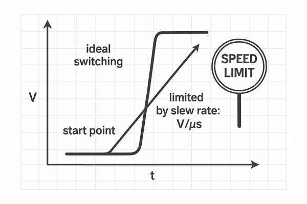
As an engineer, I've seen many designs fail because of a simple oversight: selecting an op-amp that's fast enough on paper but can't handle the required voltage swing in the real world. This crucial parameter, the slew rate, often separates a clean, reliable signal from a distorted mess. Understanding this relationship is key to building robust analog circuits. Let's explore why this happens and how to get it right.
What Is Slew Rate in an Operational Amplifier?
Struggling with slow-responding op-amp circuits? The problem might be the slew rate, a fundamental limitation you can't ignore. It dictates the true speed of your amplifier under real-world conditions.
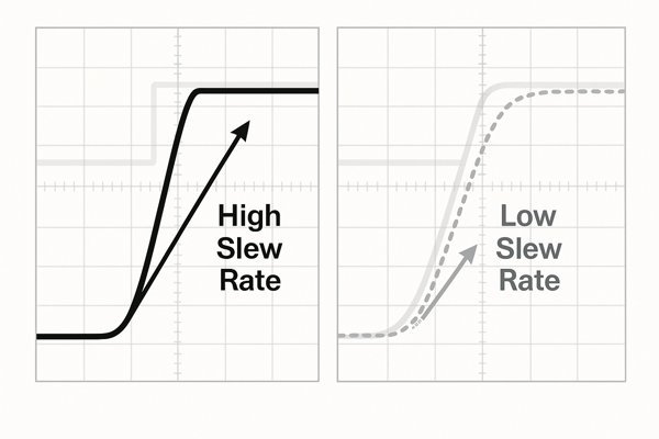
Slew rate (\(SR\)) is the maximum rate of change of an operational amplifier's output voltage. It is typically expressed in units of volts per microsecond (\(\text{V/µs}\)). This parameter represents the fastest that the op-amp's output can swing from one voltage level to another, regardless of its bandwidth.
Internal Causes and Advanced Slew Rate Concepts
At its core, the slew rate limitation in a conventional Voltage-Feedback Amplifier1 (VFA) comes from the internal architecture. The input differential pair has a finite tail current (\(I_{tail}\)) that drives the subsequent gain stage, which includes the Miller compensation capacitor (\(C_{c}\)) needed for stability. When a large, fast input step occurs, one side of the input pair cuts off, and the entire tail current is directed to charging or discharging \(C_{c}\).
This relationship is described by the formula: \(SR = \frac{I_{tail}}{C_{c}}\). This reveals a fundamental design trade-off: increasing \(C_{c}\) improves stability (phase margin) but directly worsens the slew rate. For engineers working with high-speed signals, it's crucial to understand the differences between amplifier architectures.
| Feature | Voltage-Feedback Amplifier (VFA) | Current-Feedback Amplifier2 (CFA) |
|---|---|---|
| Slew Rate Determined By | Internal tail current (\(I_{tail}\)) and compensation capacitor (\(C_{c}\)). | Output buffer's current drive and internal impedances. |
| Slew Rate Dependency | Largely independent of gain. | Also largely independent of gain. |
| Bandwidth Dependency | Bandwidth is inversely proportional to gain (Gain-Bandwidth Product). | Bandwidth is relatively independent of gain, set by a feedback resistor. |
| Typical Slew Rates | \(0.5 \text{ V/µs}\) (General Purpose) to \(>2000 \text{ V/µs}\) (High Speed). | \(>1000 \text{ V/µs}\) to \(>8000 \text{ V/µs}\). |
| Key Characteristic | Symmetrical slew rate is common but not guaranteed. | Often has extremely high, though sometimes asymmetrical, slew rates. |
What Is the Difference Between Rise Time and Slew Rate?
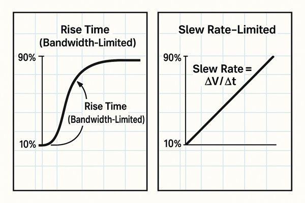
Confused about why your large-signal rise time is much slower than your small-signal one? You're likely seeing the difference between a bandwidth-limited response and a slew-rate-limited response. They are not the same.
Rise time is the time it takes for a signal to go from 10% to 90% of its final value. Slew rate is the maximum speed at which the voltage can change. For small signals, rise time is determined by bandwidth; for large signals, it is often limited by the slew rate.
Impact on Settling Time: The Hidden Cost of Slew Limiting
The key distinction lies in the signal's amplitude and the resulting required \(dV/dt\).
A critical point for experienced engineers is the impact on settling time3. Slew-rate limiting is a non-linear event that injects energy into the system. As the amplifier exits slewing, it can exhibit significant overshoot and ringing, dramatically increasing the time it takes to settle to its final value. For a 16-bit ADC driver or a DAC output, a long settling time can completely ruin the circuit's precision.
| Condition | Limiting Factor | Output Shape | Key Consequence |
|---|---|---|---|
| Small Output Swing | Bandwidth | Exponential | Predictable rise time based on BW. |
| Large Output Swing | Slew Rate | Linear Ramp | Increased settling time and signal distortion. |
What Is the Formula to Calculate the Required Slew Rate for a Sine Wave?
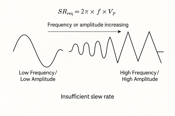
Designing an audio or signal-generation circuit? If you don't calculate the required slew rate, your clean sine wave could turn into a distorted triangle wave at higher frequencies or amplitudes.
To avoid distortion, the op-amp's slew rate must be greater than the maximum rate of change of your desired sine wave output. The formula to calculate the minimum required slew rate is: \(SR_{req} = 2 \pi \times f \times V_{p}\)
Extending the Calculation to Other Common Waveforms
While the sine wave formula is fundamental, real-world signals are more complex. Calculating the required slew rate for other common waveforms is essential for a robust design.
| Waveform | Required Slew Rate Formula | Notes |
|---|---|---|
| Sine Wave | \(SR_{req} = 2 \pi \times f \times V_{p}\) | \(V_{p}\) is the peak amplitude. |
| Square Wave | \(SR_{req} > \frac{0.8 \times V_{pp}}{t_{r}}\) | Based on desired rise time (\(t_{r}\)). |
| Triangle Wave | \(SR_{req} = 2 \times f \times V_{pp}\) | \(V_{pp}\) is the peak-to-peak voltage. |
Let's use a more demanding example. I was designing a driver for an Arbitrary Waveform Generator4 (AWG) that needed to produce a \(10 \text{ Vpp}\) (\(5 \text{ V}\) peak) sine wave at \(10 \text{ MHz}\).
\(SR_{req} = 2 \pi \times (10 \times 10^6 \text{ Hz}) \times 5 \text{ V}\)
\(SR_{req} \approx 314 \times 10^6 \text{ V/s} = 314 \text{ V/µs}\)
Here, a standard op-amp is useless. I had to select a high-speed part like the THS3091, which offers a slew rate of \(2300 \text{ V/µs}\), providing a comfortable design margin.
What Happens to an Output Signal When It Becomes Slew-Rate Limited?
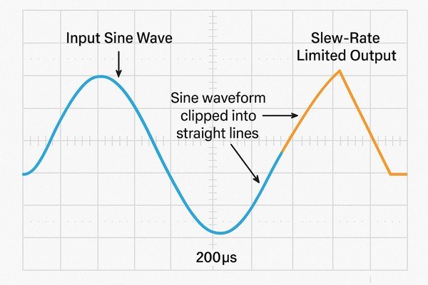
Ever seen a smooth sine wave mysteriously transform into a sharp, triangular one on your oscilloscope? This is the classic signature of slew-rate limiting, a common headache in high-frequency or high-amplitude amplifier design.
When an op-amp becomes slew-rate limited, its output signal distorts because it cannot change voltage fast enough to follow the input. A sine wave will begin to look like a triangle wave, and a fast-rising square wave will become a linear ramp.
Quantifying Slew-Induced Distortion: Harmonics and TIM
The nature of this distortion is specific and predictable. A slew-limited signal doesn't just look different; its frequency content is fundamentally altered.
| Original Signal | Slew-Limited Waveform | Primary Distortion Introduced |
|---|---|---|
| Sine Wave | Triangle Wave | Strong odd harmonics (3rd, 5th, 7th...). |
| Square Wave | Trapezoidal Wave | Slowed rise/fall times; reduced high-frequency content. |
| Complex Signal | Distorted Waveform | Transient Intermodulation Distortion (TIM). |
Transient Intermodulation Distortion (TIM)5 is a particularly insidious effect. It occurs when a complex signal containing both slow-moving components and fast transients (like a voice mixed with a cymbal crash) is passed through an amplifier with an insufficient slew rate. The fast transient forces the amplifier into slew limiting. While slewing, the amplifier's feedback loop is effectively open, causing it to ignore the lower-frequency parts of the signal, leading to a harsh, unpleasant sound.
How Does Slew Rate Impact the Full-Power Bandwidth of an Amplifier?
Wondering why your amplifier can't deliver its maximum voltage swing at its specified bandwidth? The culprit is the slew rate, which defines a different, more restrictive specification: the full-power bandwidth.
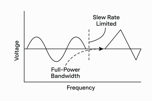
Slew rate directly limits the maximum frequency at which an amplifier can produce its maximum undistorted output voltage swing. This frequency is called the full-power bandwidth (\(f_{p}\)), and it is often significantly lower than the small-signal bandwidth.
Full-Power Bandwidth vs. Output Swing: A Practical Analysis
The full-power bandwidth (FPBW) is arguably a more honest measure of an op-amp's speed for any application that isn't purely small-signal. We can calculate it by rearranging the slew rate formula:
\(f_{p} = \frac{SR}{2 \pi \times V_{p,max}}\)This formula shows that FPBW is not a single number but a function of your output amplitude. Using the OP07 op-amp (\(SR = 0.3 \text{ V/µs}\)) as an example, we can see this trade-off clearly:
| Desired Peak Output (\(V_{p}\)) | Calculation | Resulting FPBW (Approx.) |
|---|---|---|
| \(13 \text{ V}\) (Max Swing) | \(\frac{0.3 \text{ V/µs}}{2 \pi \times 13 \text{ V}}\) | \(3.7 \text{ kHz}\) |
| \(5 \text{ V}\) | \(\frac{0.3 \text{ V/µs}}{2 \pi \times 5 \text{ V}}\) | \(9.6 \text{ kHz}\) |
| \(1 \text{ V}\) | \(\frac{0.3 \text{ V/µs}}{2 \pi \times 1 \text{ V}}\) | \(47.7 \text{ kHz}\) |
This table clearly illustrates that to get a higher frequency output, you must reduce the voltage swing to stay within the amplifier's slew-rate capability.
How Is an Op-Amp Selected Based on Its Slew Rate?
Picking the right op-amp feels overwhelming, but for high-speed or large-signal applications, slew rate is a primary filter that prevents critical design failures.
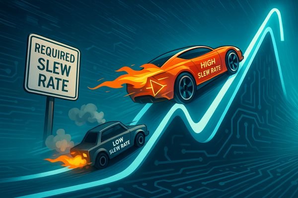
First, calculate the maximum slew rate your application requires. Then, select an op-amp with a datasheet slew rate that is significantly higher to provide a robust safety margin against real-world operating conditions and component variations.
Beyond the Formula: A Robust Selection Methodology
A "5x to 10x" rule for a safety margin is a good start, but an experienced engineer must understand why. The margin accounts for several factors that can degrade performance from the "typical" datasheet value.
| Factor | Description |
|---|---|
| Process Variations | The "minimum" slew rate spec can be 30-50% lower than the "typical" value. |
| Operating Temperature | Performance degrades at temperature extremes. Check datasheet graphs. |
| Supply Voltage | Slew rate often drops with lower supply voltages. |
| Capacitive Loading | Driving a heavy capacitive load requires high output current, which can reduce the effective slew rate. |
Considering these factors and the application's specific needs is crucial for a successful design.
| Application | Required SR (Typical) | Key Consideration | Example Part | Architecture |
|---|---|---|---|---|
| High-Fidelity Audio | \(1-10 \text{ V/µs}\) | Low TIM, Low THD+N | OPA1612 (\(50 \text{ V/µs}\)) | VFA |
| 16-Bit ADC Driver | \(50-500 \text{ V/µs}\) | Fast Settling Time, Low Distortion | ADA4945-1 (\(3900 \text{ V/µs}\)) | VFA (FDA) |
| HD Video Line Driver | \(200-1000 \text{ V/µs}\) | Differential Gain/Phase, Drives 75Ω | LMH6702 (\(3100 \text{ V/µs}\)) | CFA |
| Pulse/AWG Buffer | \(>1000 \text{ V/µs}\) | Max Slew Rate, Rise Time | THS3491 (\(8000 \text{ V/µs}\)) | VFA (High-Speed) |
Conclusion
In short, slew rate is the ultimate speed limit for your op-amp's output. Ignoring it leads to signal distortion and settling time issues. Always calculate your needs and choose a part with a healthy margin.
-
Exploring this link will provide insights into the design and functionality of VFAs, crucial for effective circuit design. ↩
-
Learn how Current-Feedback Amplifiers work, their advantages, and why they offer higher slew rates compared to traditional Voltage-Feedback Amplifiers. ↩
-
Understanding settling time is crucial for optimizing circuit performance and ensuring precision in electronic designs. ↩
-
Exploring how AWGs function can enhance your design skills and help you select the right components for your projects. ↩
-
Understanding TIM is crucial for audio engineers to prevent harsh sounds in complex signals. Explore this link for in-depth insights. ↩


