Your new product works perfectly on the bench, but it fails certification right before launch. Now you're facing costly redesigns and major project delays. Understanding and planning for EMC testing from the start is the only way to avoid this engineering nightmare.
Electromagnetic Compatibility (EMC) testing is a series of procedures that verify your electronic device can function correctly in its electromagnetic environment. It ensures the device doesn't produce excessive electromagnetic interference (EMI) and can withstand a certain level of interference from other sources without malfunctioning.
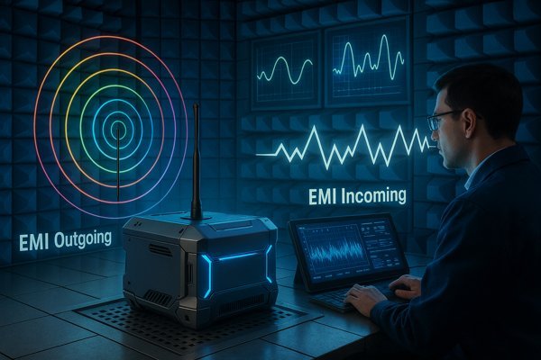
Getting EMC right is not just about passing a test; it’s a fundamental part of designing a robust and reliable product that can be legally sold and will function as expected in the real world. Many engineers, especially those early in their careers, get tangled in the terminology and requirements. Let's break down the core concepts to build a solid foundation. This knowledge is what separates a smooth product launch from a costly failure.
What is the difference between EMC, EMI, and EMS?
Are you confused by the alphabet soup of EMC, EMI, and EMS? This confusion isn't just academic; it can lead to critical design mistakes. Let's clarify these fundamental terms.
EMC (Electromagnetic Compatibility) is the overall goal. EMI (Electromagnetic Interference) is the problem—unwanted noise your device creates. EMS (Electromagnetic Susceptibility) is your device's vulnerability to external noise. EMC is achieved when your device's EMI is low and its resistance to EMS is high.
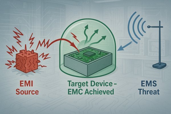
To truly grasp this, let's think critically about their relationship. They are not separate concepts but three sides of the same coin. An effective engineer doesn't just define them; they understand how they interact in a real product.
An Analogy: A Conversation in a Crowded Room
Imagine you're trying to talk to a friend in a noisy restaurant.
- EMI (Interference): This is the noise your device creates. It's like you talking so loudly that you disrupt other people's conversations around you. This includes both unintentional noise from your processor and intentional transmissions from its radio.
- EMS (Susceptibility): This is your device's vulnerability to noise. It's your inability to hear your friend because of the loud background chatter from other tables.
- EMC (Compatibility): This is the ideal state where everyone can coexist. You are speaking at a reasonable volume, and you can still hear your friend clearly despite the ambient noise. Your device is both a "good neighbor" and "robust."
The core engineering challenge is to balance these. You must design your product to be "quiet" (low EMI) and "a good listener" (low EMS, or high immunity).
| Term | Full Name | Focus | Role in the System |
|---|---|---|---|
| EMC | Electromagnetic Compatibility | The overall desired state | The goal: Coexistence. |
| EMI | Electromagnetic Interference | The "cause" or the noise emission | The problem to be controlled. |
| EMS | Electromagnetic Susceptibility | The "effect" or the vulnerability | The weakness to be hardened. |
Why is EMC testing important?
Do you think EMC testing is just another bureaucratic hurdle to clear? Ignoring its importance can lead to product recalls, legal fines, and a damaged brand reputation. Let's explore why it's absolutely critical.
EMC testing is essential for three main reasons: it ensures legal compliance required to sell products in major markets, it guarantees product reliability in real-world environments, and it protects your brand's reputation by preventing your product from interfering with others.
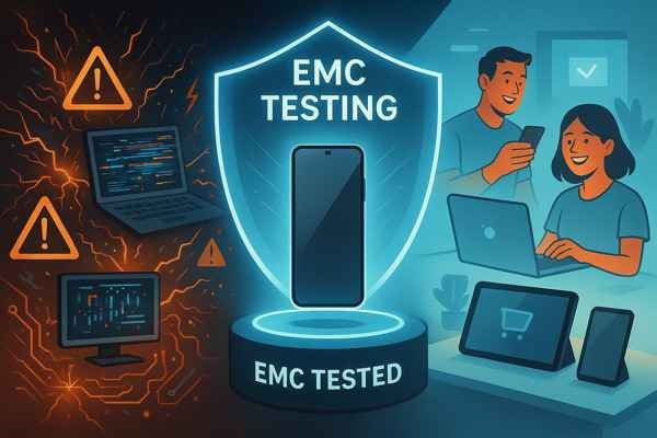
These three reasons are not just bullet points; they represent the intersection of engineering, law, and business. A failure in EMC is a failure in all three areas.
Legal and Regulatory Compliance
This is the most straightforward reason: it's the law. You cannot legally place most electronic products on the market in the US, Europe, or many other parts of the world without proof of EMC compliance. At Honeywell, when we designed the Tuxedo Keypad for a global rollout, we didn't have a choice. We had to pass FCC in the US, CE in Europe, and other standards for markets like Australia. A failure wasn't a suggestion to improve; it was a hard gate that would block millions in revenue. These regulations, like the EU's EMC Directive 2014/30/EU and the US's FCC Part 15, exist to prevent electronic chaos.
Product Reliability and Functionality
Beyond legal requirements, EMC ensures your product actually works. A device that is overly susceptible to interference is a defective device. When I led hardware development for a next-generation infusion pump, immunity was paramount. If that pump malfunctioned because a doctor used their cell phone nearby, the consequences could be life-threatening. The same principle applies in industrial automation: if EMI from a high-power motor drive corrupts the data from a nearby process sensor, it can halt an entire production line, costing thousands of dollars per minute. EMC testing verifies your design is robust enough for its intended, and often harsh, environment.
Brand Reputation and Commercial Success
Finally, good EMC is good business. A product that constantly resets, or worse, disrupts other devices in a customer's home—like their Wi-Fi router or garage door opener—will quickly earn a reputation for being cheap and unreliable. This leads to negative reviews, high product return rates, and long-term damage to your brand's credibility. Investing in good EMC design is investing in customer satisfaction and the perception of quality.
What are the main types of EMC tests?
Feeling overwhelmed by the sheer number of different EMC tests? Not understanding the key categories can make your test plan confusing and incomplete. Here is a simple breakdown of the main types.
The main types of EMC tests fall into two primary categories: Emissions testing, which measures the unwanted electromagnetic noise your device generates, and Immunity (or Susceptibility) testing, which evaluates how well your device withstands external electromagnetic phenomena.
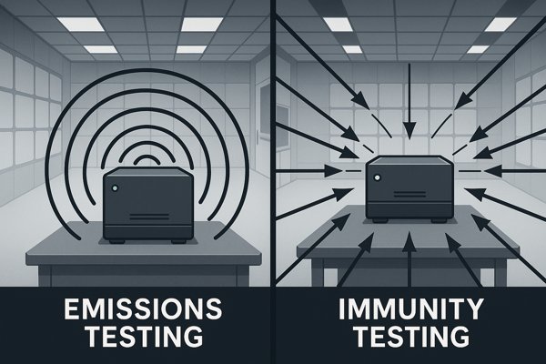
These two categories form the foundation of all EMC work. It's also helpful to understand that standards are either "generic" or "product-specific." Generic standards like the IEC 61000 series apply broadly, while product-specific standards like CISPR 32 for multimedia equipment or CISPR 25 for vehicles tailor the requirements to a specific environment. You must identify which applies to your product.
Emissions Testing: Being a Good Neighbor
The goal here is to ensure your product doesn't pollute the electromagnetic spectrum. You are measuring the "noise" it outputs.
- Radiated Emissions1: Measures noise leaving your product through the air.
- Conducted Emissions2: Measures noise leaving your product through its connected cables (e.g., power cord).
Immunity Testing3: Being Robust
The goal here is to ensure your product can survive in a noisy world. You are testing its ability to withstand incoming energy without malfunctioning.
- Radiated Immunity: Tests resistance to noise fields arriving through the air.
- Conducted Immunity: Tests resistance to noise arriving on its cables.
- Specialized Tests: This category also includes tests for common environmental events like static electricity (ESD), power line surges, and fast transients (EFT).
| Category | Path | Test Type | Purpose | Common Standard (Test Method) |
|---|---|---|---|---|
| Emissions | Radiated (Air) | Radiated Emissions | Measure RF noise broadcast by the device. | CISPR 16 / ANSI C63.4 |
| Conducted (Cable) | Conducted Emissions | Measure RF noise on power/signal lines. | CISPR 16 / ANSI C63.4 | |
| Immunity | Radiated (Air) | Radiated Immunity | Test resistance to external RF fields. | IEC 61000-4-3 |
| Conducted (Cable) | Conducted Immunity | Test resistance to RF noise on cables. | IEC 61000-4-6 | |
| Contact/Air | Electrostatic Discharge (ESD) | Test resistance to static electricity. | IEC 61000-4-2 | |
| Conducted (Cable) | Electrical Fast Transient (EFT) | Test resistance to power line bursts. | IEC 61000-4-4 | |
| Conducted (Cable) | Surge | Test resistance to power line surges. | IEC 61000-4-5 |
What is the difference between radiated and conducted emissions?
Does your device leak unwanted noise through the air or down its power cord? Misunderstanding this critical difference can lead you to apply the wrong filtering or shielding solution, wasting time and money.
Radiated emissions are unwanted electromagnetic energy that your device broadcasts through the air like a tiny radio station. Conducted emissions are unwanted energy that travels along the power cords or signal cables connected to your device.
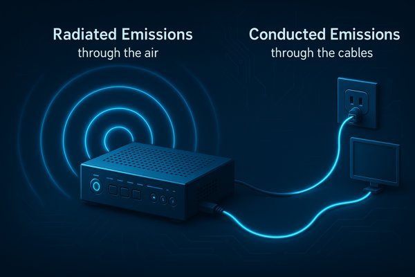
While the definitions are simple, the engineering implications are distinct. The frequency ranges, sources, and solutions for each are completely different.
Radiated Emissions: The High-Frequency Problem
This is primarily a high-frequency issue where PCB traces and cables act as antennas. The noise comes in two forms: differential-mode (from small loops on the PCB) and common-mode (from entire cables acting as antennas). Common-mode is usually the bigger problem.
- Frequency Range: Typically measured from \(30 \text{ MHz}\) to \(1 \text{ GHz}\) or higher, per standards like CISPR 32.
- Common Sources: High-speed clocks, data lines, and attached I/O cables.
- Solutions: Good PCB layout (solid ground planes), shielding, and filtering on I/O lines to block common-mode currents from reaching the cables.
Conducted Emissions: The Low-Frequency Problem
This is a power-line contamination problem, again with two forms: differential-mode (noise between the Line and Neutral wires) and common-mode (noise from Line/Neutral to Earth Ground). A good filter must address both.
- Frequency Range: A lower-frequency problem, typically measured from \(150 \text{ kHz}\) to \(30 \text{ MHz}\).
- Common Sources: The #1 source is the switching-mode power supply (SMPS)4.
- Solutions: A well-designed power entry filter with both X-capacitors (for differential) and Y-capacitors5 plus a common-mode choke (for common-mode).
| Feature | Radiated Emissions | Conducted Emissions |
|---|---|---|
| Path | Through the air (wireless) | Along cables (wired) |
| Frequency Range | High (e.g., \(30 \text{ MHz} – 6 \text{ GHz}\)) | Low (e.g., \(150 \text{ kHz} – 30 \text{ MHz}\)) |
| Typical Cause | Common-mode currents on cables, PCB loops | Switching power supplies (SMPS) |
| Primary Solution | Good PCB layout, shielding | Power line filtering (inductors, capacitors) |
What is the difference between radiated and conducted immunity?
Your device passed all emissions tests, but it resets every time a security guard keys up their walkie-talkie nearby. This is an immunity problem. Let's distinguish between the two primary immunity challenges.
Radiated immunity is a device's ability to withstand electromagnetic fields coming from external sources through the air. Conducted immunity is its ability to withstand electrical disturbances traveling along its power and data cables.
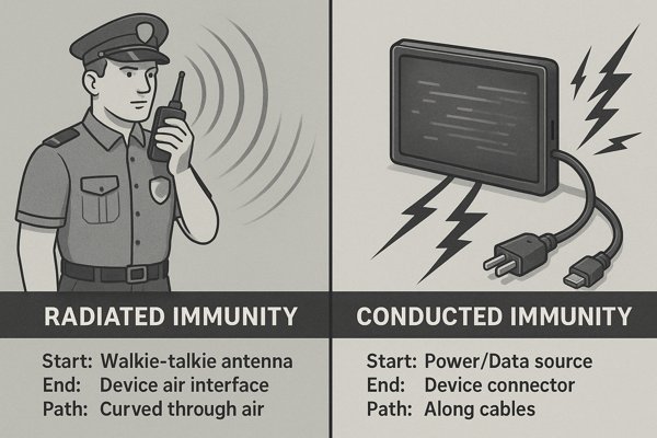
Just as with emissions, understanding the path of the interference is key to designing a robust product. A design might be well-shielded against radiated fields but have no protection against noise coming in through its power cord. The key differences are summarized below.
| Feature | Radiated Immunity | Conducted Immunity |
|---|---|---|
| Path of Interference | Through the air | Along connected cables |
| Frequency Range | High (e.g., \(80 \text{ MHz} – 2.7 \text{ GHz}\)) | Low (e.g., \(150 \text{ kHz} – 80 \text{ MHz}\)) |
| Test Method | Illuminate with an antenna (IEC 61000-4-36) | Inject noise with a probe/CDN (IEC 61000-4-67) |
| Simulates | Cell phones, two-way radios, broadcast towers | Noise from power grid, other equipment |
| Primary Solution | Shielding (enclosure), PCB-level filtering | Filtering at cable entry points (ferrites, caps) |
The test signal for Radiated Immunity (per IEC 61000-4-3) is typically amplitude modulated with a \(1 \text{ kHz}\) sine wave at \(80\%\) depth. This simulates real-world signals and is more likely to be rectified by semiconductor junctions, causing disruption. For Conducted Immunity (per IEC 61000-4-6), the test stops at \(80 \text{ MHz}\) because above this frequency, cables become much more efficient as receiving antennas for radiated fields, a phenomenon covered by the radiated immunity test.
When in the product design process should I consider EMC?
Are you waiting until your prototype is built to start thinking about EMC? That's a classic, and very expensive, mistake. Let's pinpoint exactly when you need to start designing for compliance.
You must consider EMC from day one of the product design process. It is not a final step or a separate task. It must be an integral part of component selection, schematic design, and especially PCB layout. The later you address it, the harder and more expensive it is to fix.
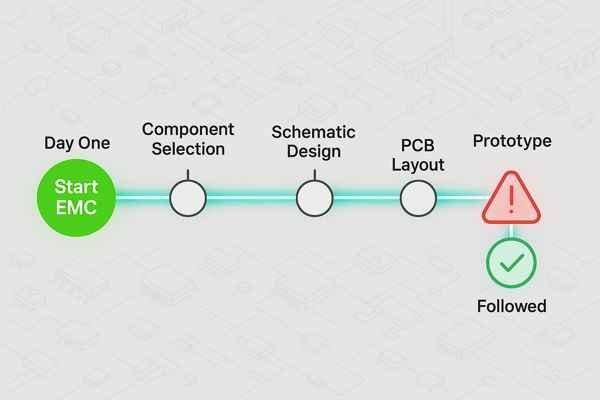
Fixing an EMC problem with "band-aids" like copper tape and last-minute ferrite beads is a sign of failed planning. True EMC engineering is proactive, not reactive. It must be woven into every stage of development, as summarized in the table below.
| Design Stage | Key EMC Actions | Primary Goal |
|---|---|---|
| 1. Architecture | Select shielded enclosures, low-EMI processors. Partition noisy and sensitive zones. | Make high-level choices that prevent problems before they start. |
| 2. Schematic | Design in filters on all power and I/O lines. Plan the grounding strategy. | Ensure all potential noise paths are controlled at the component level. |
| 3. PCB Layout | Use a solid ground plane stack-up. Keep traces short. Manage return paths. | Minimize the "antenna efficiency" of the PCB itself. This is critical. |
Following this staged approach is far more effective than trying to solve everything at the end. For example, in PCB layout, use \(45^{\circ}\) bends instead of \(90^{\circ}\) corners on high-speed traces and use stitching vias8 generously to connect ground planes together, especially along board edges, forming a mini "Faraday cage." These small layout details, decided early, can make the difference between passing and failing.
What are the most common EMC standards?
Are you unsure which EMC rules your product has to follow? Launching a product without knowing the right standards can get it blocked by customs or pulled from shelves. Let's demystify the key regulations.
The most common standards depend on your target market. In the USA, it's FCC Part 15. For the European Union, it's the CE mark, which relies on EN (European Norm) standards that are harmonized with international CISPR and IEC standards.
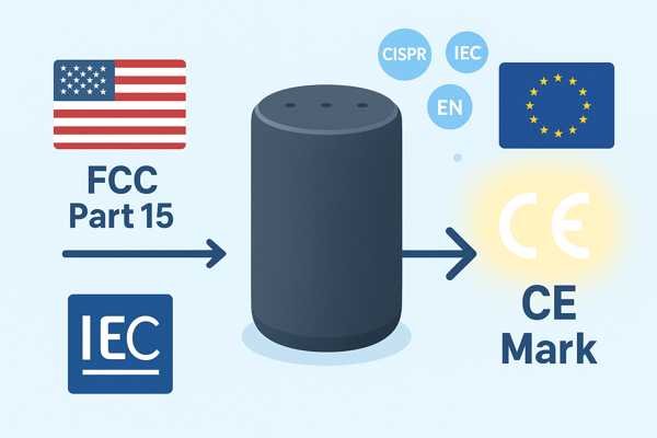
Think of the standards landscape as a pyramid. At the top are regional legal requirements. These requirements reference specific product family standards, which in turn reference fundamental test method standards.
The International Foundation: IEC and CISPR
- IEC (International Electrotechnical Commission): They write the "how-to" standards for testing, like the IEC 61000 series.
- CISPR (International Special Committee on Radio Interference): They create product-level emission standards like CISPR 32 (multimedia) that are adopted globally.
Regional and Industry-Specific Implementations
This is what most engineers interact with directly. While FCC and CE are common, be aware of others.
- Automotive: Standards like CISPR 25 are used by vehicle manufacturers and are much stricter than consumer standards.
- Aerospace & Military: The MIL-STD-461 standard is the benchmark, with extremely stringent requirements for both emissions and susceptibility.
| Region / Mark | Governing Body | Key Standards (for a typical product) | Key Distinction |
|---|---|---|---|
| USA (FCC) | Federal Communications Commission | FCC Part 159, Subpart B (for unintentional radiators) | Class A vs. Class B. Class B (residential) has much stricter emission limits than Class A (commercial/industrial). |
| Europe (CE) | European Union | EN 5503210 (Emissions, from CISPR 32) EN 5503511 (Immunity, from CISPR 35) | The CE mark is a self-declaration. You must have a test report to back up your claim. |
How do I prepare a product for EMC testing?
Showing up at the test lab unprepared is one of the fastest ways to waste thousands of dollars. An unsuccessful test day means you pay for lab time without getting a result. Here’s how to prepare.
To prepare for EMC testing, create a detailed test plan, bring at least two fully operational Devices Under Test (DUTs), provide all necessary support equipment and cables, and pack a "debug kit" with components for on-the-spot fixes.
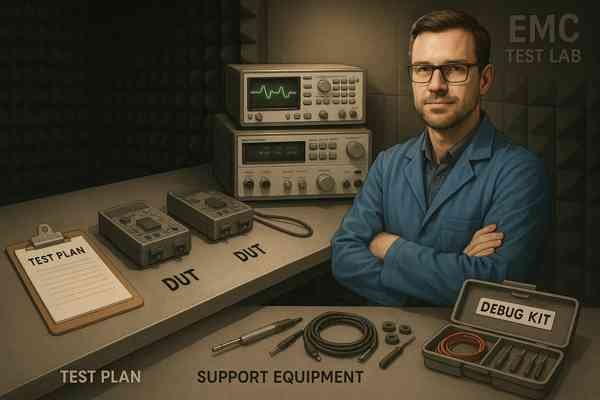
Your goal on test day is to execute efficiently. Good preparation transforms the test from a pass/fail event into a valuable engineering exercise.
1. Documentation: The Test Plan
This is your contract with the test lab. It must be clear and comprehensive.
- Operating Modes: Define a specific firmware build that represents the "worst-case" emissions.
- Monitoring Methods: How will the lab know if the DUT is still working during an immunity test? You must define this. Examples: "Continuously ping the Ethernet port," "Monitor video output for distortion," or "Verify a specific memory location remains unchanged."
- Acceptance Criteria: Clearly define pass/fail. Is a single-pixel flicker on the display a failure? The lab cannot make this judgment for you.
2. Hardware: The DUT and Support Gear
Come over-prepared. The one cable you forget will be the one you need.
- Multiple DUTs: Bring at least two. One for the official test, one as a backup, and a third you can modify for debug without stopping the test.
- Cables: Bring all required cables, specifically the longest length you intend to sell.
3. The On-Site Debug Kit
If you fail, the day isn't a total loss if you can find the source. Your kit should be organized and ready.
| Category | Item(s) | Purpose |
|---|---|---|
| Filtering | Snap-on ferrites, SMD ferrite beads & caps | Suppressing common-mode noise on cables and PCB traces. |
| Shielding | Copper foil tape with conductive adhesive, gaskets | Temporarily closing shield gaps or grounding enclosures. |
| Tools | Soldering iron, hand tools, multimeter | Modifying the DUT to test potential fixes. |
| Diagnostics | Near-field probes (H-field & E-field) | "Sniffing" the PCB to find the exact source of radiation. |
| Documentation | Laptop with schematics and layout files | Cross-referencing board locations with the design. |
What are the most common reasons for failing EMC tests?
Your product just failed its radiated emissions test. It's a frustrating but common experience. Understanding the usual suspects can help you design them out from the very beginning.
The most common reasons for failing EMC tests are poor PCB layout, especially inadequate grounding; unshielded or improperly terminated cables acting as antennas; noisy switching power supplies; and poor power integrity with inadequate decoupling.
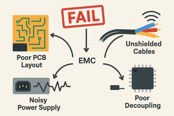
In nearly two decades of hardware engineering, I've seen that EMC failures are rarely caused by exotic issues. They are almost always a result of overlooking a few fundamental principles, which are summarized in the debugging table below.
| Failure Symptom | Most Likely Cause | Common Root Cause & Fix |
|---|---|---|
| Radiated Emissions Failure | Cables | Common-mode currents are escaping. Fix: Add snap-on ferrites or improve shield termination. |
| Radiated Emissions Failure | PCB Direct Radiation | A high-speed trace has a broken return path (split ground). Fix: Redesign layout to ensure a solid ground return. |
| Conducted Emissions Failure | Power Supply | Inadequate input filtering on the SMPS. Fix: Improve the power entry filter (chokes/capacitors). |
| Immunity Failure (any type) | Sensitive Circuit | Noise is coupling into a high-impedance analog trace or reset line. Fix: Add filtering, improve shielding. |
The link between Power Integrity (PI)12 and EMC is often overlooked. If an IC, like a processor, doesn't have enough nearby decoupling capacitors, its demand for high-frequency current will cause the power rails to ring. This high-frequency noise on the power distribution network (PDN) can then easily radiate from the board, causing an emissions failure.
How much does EMC testing cost?
Are you worried about the high cost of EMC testing? The price tag can seem intimidating, but the cost of not testing—or failing and having to redesign—is far, far higher. Let's break down the real numbers.
A single day of pre-compliance testing at a lab can cost $1,500 to $3,000. Full compliance testing for a standard product targeting both FCC (USA) and CE (Europe) certification typically ranges from $10,000 to $25,000, depending on complexity.

This cost reflects the millions of dollars invested in the specialized equipment and facilities. When evaluating the cost, you must also consider the hidden costs of failure.
The Hidden Costs of Failure
The real cost of an EMC failure isn't just the re-test fee. It's the sum of:
- Re-Test Cost: Another $10k - $25k.
- Engineering Time: Weeks of expensive engineering salaries spent debugging and redesigning.
- Prototype Costs: The cost of a new PCB spin and assembly.
- Opportunity Cost: This is often the biggest financial hit. A three-month launch delay means three months of lost sales and giving competitors a head start. This can easily run into hundreds of thousands of dollars.
Sample Cost Breakdown
This is a rough estimate for a moderately complex, non-wireless product.
| Test Suite | Estimated Cost (USD) | What's Included |
|---|---|---|
| Pre-Compliance (Optional) | $2,000 - $3,500 | 1 day of engineering-level investigation. |
| Emissions | $4,000 - $7,000 | Radiated & Conducted Emissions tests. |
| Immunity & Transients | $8,000 - $16,000 | Radiated/Conducted Immunity, ESD, EFT, Surge. |
| Total (Full Compliance) | $12,000 - $23,000 | Full compliance package for CE and/or FCC. |
How long does the EMC testing process take?
Is your project timeline being held hostage by EMC testing? The process can seem like a black box that delays your launch. Let's shed light on how much time you should realistically budget for it.
The active testing time for a typical product might take 3 to 5 full days in the lab. However, the entire process—from scheduling a lab to receiving the final certified report—usually takes 2 to 4 weeks, and that’s only if your product passes on the first attempt.
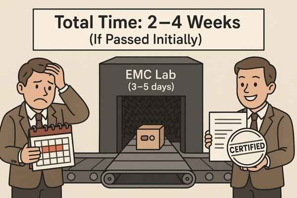
The most common project management mistake is to only schedule the 3-5 days of active testing. The reality includes significant lead time and post-test reporting that must be factored into any credible project plan. The table below illustrates the stark difference in timelines between a pass and a fail.
| Process Step | "Best Case" Timeline (Pass) | "Worst Case" Timeline (Fail) |
|---|---|---|
| Lab Scheduling | 2-6 weeks | 2-6 weeks |
| Initial Testing | 1 week | 1 week |
| Debug & Redesign | N/A | 3-6 weeks |
| Re-Scheduling Lab | N/A | 2-4 weeks |
| Re-Testing | N/A | 1 week |
| Final Report | 1-2 weeks | 1-2 weeks |
| TOTAL | ~4-9 weeks | ~10-20 weeks |
As you can see, a single EMC failure can easily push a product launch back by an entire quarter. This is the strongest possible argument for investing in good up-front EMC design.
How do I find a certified EMC testing lab?
You need to get your product tested, but how do you find a lab you can trust? Choosing an unaccredited or unqualified lab can result in an invalid test report, meaning your product could be rejected by regulators.
To find a certified lab, search the online databases of accreditation bodies like A2LA (American Association for Laboratory Accreditation) or NVLAP in the USA. The most critical step is to check the lab's "Scope of Accreditation" to ensure it covers the specific standards you need.

Accreditation is the formal recognition that a laboratory is competent, impartial, and operates according to international standards. An accredited report carries weight with regulatory bodies worldwide.
Step 1: Identify Your Required Standards
Before you can find a lab, you must know what you're testing for. Is it FCC Part 15? Is it EN 55032? This list of standards is your primary search criteria.
Step 2: Search Accreditation Body Databases
These databases are the authoritative source for finding qualified labs.
- A2LA Directory: (customer.a2la.org)
- NVLAP Directory: (nist.gov/nvlap)
- FCC Recognized Test Firm Search: (fcc.gov)
Step 3: Scrutinize the "Scope of Accreditation"
This is the most critical step. Every accredited lab has a public "Scope of Accreditation." This document lists every single test standard the lab is certified to perform. Verify that your required standard (e.g., "CISPR 32") is on that list and that the accreditation is current. Before signing a contract, you can also ask the lab for an anonymized sample report for a similar product. This lets you judge the quality and thoroughness of their documentation.
Conclusion
EMC is not a final hurdle to jump over, but a core engineering discipline. Understanding the tests, standards, and design principles from the very beginning is what separates a smooth, on-time product launch from a cycle of costly failures and delays.
-
Understanding Radiated Emissions is crucial for ensuring compliance and reducing interference in electronic devices. ↩
-
Learn how conducted emissions can affect your product's compliance and discover best practices for minimizing unwanted RF noise on power and signal lines. ↩
-
Learn how immunity testing ensures your electronic products can withstand real-world electromagnetic disturbances and remain reliable. ↩
-
Exploring SMPS will help you grasp its impact on conducted emissions and improve your power supply designs. ↩
-
Learn how X-capacitors and Y-capacitors function in power line filters to effectively reduce differential and common-mode noise in electronic devices. ↩
-
Learn how IEC 61000-4-3 defines radiated immunity testing standards to ensure your products are robust against electromagnetic interference. ↩
-
Learn how IEC 61000-4-6 defines standards for conducted immunity testing, crucial for ensuring your product's resilience against cable-borne interference. ↩
-
Exploring the role of stitching vias can enhance your PCB designs, ensuring better performance and compliance with EMC standards. ↩
-
Learn how FCC Part 15 impacts electronic device compliance and why understanding its rules is crucial for legal product sales in the US market. ↩
-
Learn what EN 55032 covers and why it's essential for ensuring your multimedia products meet European emission standards. ↩
-
Learn how EN 55035 sets immunity requirements for multimedia equipment and why compliance is crucial for CE marking in Europe. ↩
-
Understanding this relationship is crucial for effective hardware design and avoiding common pitfalls in EMC. ↩


