Struggling with mysterious high-frequency noise in your circuits? This noise can cause EMI failures and unpredictable behavior. A simple ferrite bead might be the effective, low-cost solution you need.
A ferrite bead is a passive electronic component used to suppress high-frequency noise in electronic circuits. It acts as a low-pass filter, blocking unwanted radio frequency (RF) energy on power supply lines and signal paths, while allowing DC or low-frequency signals to pass through unimpeded.
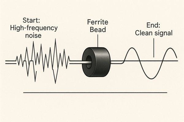
Understanding how this simple component works is key to solving tough noise problems. I've used them in countless designs, from sensitive medical devices to high-reliability aerospace systems. They are a fundamental tool, but you have to know how to select and apply them correctly. Let's dive deeper into how you can use them to make your designs more robust and pass those tricky EMC tests.
How Does a Ferrite Bead Work?
You see ferrite beads on cables and PCBs, but how do they kill noise? It can seem like magic. I'll break down the simple physics behind their function.
A ferrite bead works by presenting a high impedance to high-frequency signals. It absorbs this unwanted RF energy and dissipates it as a very small amount of heat. Unlike an ideal inductor, its primary function becomes resistive at high frequencies, which is key to its effectiveness.
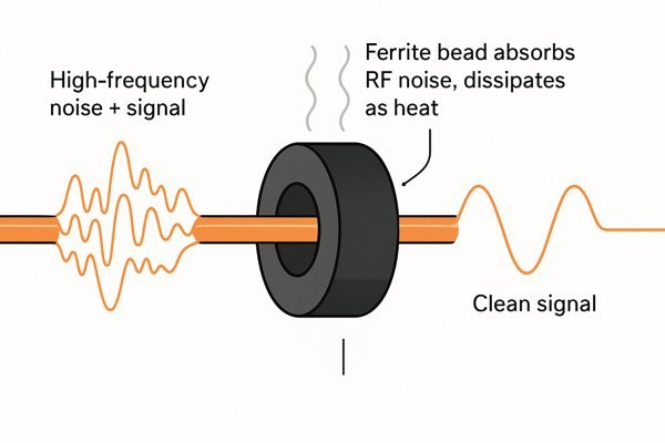
A ferrite bead’s behavior changes with frequency. Think of it like a car's suspension. An inductor is like a perfect spring: it stores and releases energy, causing the car to bounce. A ferrite bead in its useful range is like a shock absorber 🚗: it dampens the bounce by converting the motion into heat. This dissipation is exactly what you want for noise. Reflecting the noise with a purely inductive filter can sometimes cause it to pop up elsewhere in your system.
The bead's impedance curve has three distinct regions:
Ferrite Bead Impedance Characteristics
| Frequency Region | Dominant Characteristic | Behavior |
|---|---|---|
| Low Frequency | Inductive (\(X_{L}\)) | Acts like a standard inductor, stores energy. |
| Mid Frequency | Resistive (\(R\)) | Acts like a resistor, dissipates energy as heat. (This is the target region) |
| High Frequency | Capacitive (\(X_{C}\)) | Parasitic capacitance dominates, impedance drops. |
The magic happens in that middle, resistive region. The ferrite material itself is a ceramic made of iron oxides mixed with metals like nickel, zinc, or manganese. At high frequencies, the magnetic domains within this material can't switch fast enough to follow the signal. This internal friction, or magnetic hysteresis loss, converts the RF energy into heat. Your goal as a designer is to select a bead where this resistive peak aligns perfectly with the frequency of the noise you want to eliminate.
How to Choose the Right Ferrite Bead?
Choosing the wrong ferrite bead is useless, or even worse, it can harm your circuit's performance. So how do you pick the perfect one? Let's break down the process.
To choose the right ferrite bead, you must first identify the noise frequency range. Then, select a bead with high impedance at that frequency. Finally, ensure its rated DC current is higher than your circuit's operating current to avoid saturation and performance loss.

Selecting the right bead is a systematic process. I use this checklist to ensure I don't miss a critical parameter.
Ferrite Bead Selection Checklist ✅
| Design Step | Key Question to Answer | Where to Find the Answer (Datasheet) |
|---|---|---|
| 1. Analyze the Noise | What frequency range do I need to suppress? | (Measured with a spectrum analyzer1) |
| 2. Select Impedance | Does this bead have high, resistive impedance at my target frequency? | "Impedance vs. Frequency" Graph (\(Z\), \(R\), \(X\) curves) |
| 3. Verify Current Handling | Will the bead's impedance remain high enough at my circuit's operating DC current? | "Impedance vs. DC Bias Current" Graph |
| 4. Check for Voltage Drop | Is the DC Resistance (DCR)2 low enough to avoid an unacceptable voltage drop? | "DCR" specification (in \(\text{m}\Omega\)) |
| 5. (Optional) Simulate | How will the bead perform with my specific source and load impedances? | Manufacturer-provided SPICE model |
Pro-Tip: Most major manufacturers (like Würth Elektronik, Murata, TDK) provide SPICE models for their ferrite beads. Use them! Simulating the bead's performance in your circuit before you even build a prototype can save you weeks of debugging time.
How to Install a Ferrite Bead on a Cable?
You have a noisy cable causing EMI issues in the lab. A clamp-on ferrite seems easy, but does placement matter? Yes, it absolutely does. Here's how to do it right.
For best results, install the clamp-on ferrite bead as close as possible to the source of the noise. If you're trying to prevent noise from entering a device, place it directly at the equipment's cable entry point. Looping the cable through the core increases impedance.
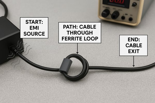
When a product fails an EMC test, a clamp-on ferrite is often the first quick fix we try. The goal is to stop RF energy from turning the cable into an antenna.
The Power of Turns
A single pass through a ferrite gives you the baseline impedance. But you can significantly increase the impedance by looping the wire through the core multiple times. The impedance scales approximately with the square of the number of turns (\(Z \propto N^2\)).
| Number of Turns (\(N\)) | Approximate Impedance Increase |
|---|---|
| 1 (single pass) | Baseline (\(Z\)) |
| 2 | \(\approx 4 \times Z\) |
| 3 | \(\approx 9 \times Z\) |
It's crucial to understand that a ferrite core clamped around a multi-conductor cable (like a USB or power cord) primarily attacks common-mode noise. This is noise where the current flows in the same direction on all conductors simultaneously.
What Is the Difference Between a Ferrite Bead and an Inductor?
Aren't they both just coils of wire around a magnetic core? This is a common point of confusion. Using them interchangeably can cause serious problems in your circuit. Let's clarify the key differences.
The main difference is their purpose. An inductor is designed to store energy with low loss (high \(Q\) factor). A ferrite bead is designed to block noise by dissipating energy as heat with high loss (low \(Q\) factor) at specific high frequencies.
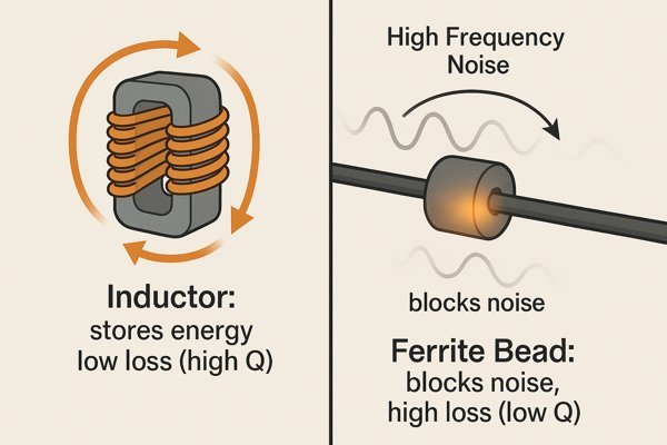
I once troubleshooted a board where an engineer had used an inductor on a power line for "filtering." It made the EMI failure worse. The inductor formed a resonant tank circuit with the board's parasitic capacitance, and its resonant peak landed right on a harmonic of the system clock, amplifying it. Swapping it for a properly chosen ferrite bead, which is resistive at that frequency, solved the problem instantly.
Ferrite Bead vs. Inductor
| Feature | Ferrite Bead | Inductor |
|---|---|---|
| Primary Function | Energy Dissipation (acts like a resistor at high frequency) | Energy Storage (acts as an inductor) |
| Intended Effect | Absorb and dissipate unwanted RF noise as heat. | Store energy in a magnetic field for use in filters or power converters. |
| Quality Factor3 (\(Q\)) | Low \(Q\) (lossy) by design in the target frequency range. | High \(Q\) (low loss) by design to minimize energy loss. |
| Primary Risk | Excessive voltage drop from DCR; saturation under DC bias. | Unwanted resonance with parasitic capacitance, which can amplify noise. |
When Should a Ferrite Bead Be Used?
You have a noise problem. Should you reach for a capacitor, an inductor, or a ferrite bead? Using the right tool for the job saves time and headaches during development.
Use a ferrite bead when you need to suppress high-frequency noise (typically above \(10 \text{ MHz}\)) on power or signal lines without affecting the DC or low-frequency signal. It's ideal for passing EMI/EMC tests and improving general signal integrity in digital and analog systems.
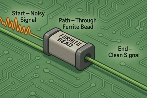
Ferrite beads are most effective in a few specific scenarios.
Common Ferrite Bead Applications
| Application Area | How It's Used | Key Design Consideration |
|---|---|---|
| Power Supply Lines | Placed in series with the power pin of an IC to form a Pi filter with capacitors. | Check DC bias saturation and voltage drop from DCR. Ensure correct layout order. |
| Signal/Data Lines | Placed in series on a signal line (e.g., clock, I2C, SPI) to filter noise. | Choose a bead that won't distort the signal. The bead's impedance should be low at the signal's fundamental frequency. |
| Cable Interfaces | Placed on I/O lines (USB, Power, etc.) right at the connector. | Suppresses common-mode noise, preventing the cable from acting as an antenna for EMI. |
What Do the Specifications of a Ferrite Bead Mean?
A ferrite bead datasheet is full of specs: impedance at \(100 \text{ MHz}\), rated current, and DCR. Ignoring these details is a recipe for failure. Let's decode what really matters for your design.
The most critical specifications are Impedance at a specific frequency (e.g., \(600 \Omega \text{ @ } 100 \text{ MHz}\)), Rated Current (the max DC current before performance degrades), and DC Resistance (DCR). The impedance versus frequency graph is the most important tool for selection.
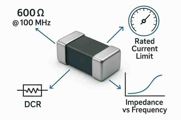
Here are the key parameters you must check.
Key Ferrite Bead Parameters
| Specification | What It Means | Why It Matters |
|---|---|---|
| Impedance @ Frequency | The bead's impedance (\(Z\)) at a standard test frequency, usually \(100 \text{ MHz}\). Example: \(1000 \Omega \text{ @ } 100 \text{ MHz}\). | This is the headline spec. It tells you the bead's strength but only at one frequency. You must look at the graph for the full story. |
| Rated Current (\(I_{rated}\)) | The maximum continuous DC current the bead can handle without significant performance loss or overheating. | Exceeding this current will cause the bead to saturate and lose its impedance. Your filter will stop working. This is a critical parameter. |
| DC Resistance (DCR) | The inherent resistance of the wire in the bead. Typically measured in milliohms (\(\text{m}\Omega\)). Example: \(50 \text{ m}\Omega\). | DCR causes a voltage drop (\(V = I \times R_{DCR}\)) and power loss (\(P = I^2 \times R_{DCR}\)). This can be a problem for low-voltage, high-current power rails. |
| Self-Resonant Freq. (SRF) | The frequency where the bead's impedance is highest. Above the SRF, the bead becomes capacitive. | You want your problem noise frequency to be at or slightly below the SRF to be in the effective resistive region. |
How Is a Ferrite Bead's Impedance Calculated or Represented?
You see a graph in a datasheet with three curves: \(Z\), \(R\), and \(X\). What does it all mean for your circuit? Understanding this graph is the key to mastering ferrite beads.
A ferrite bead's impedance isn't a single calculated number. It's represented by a graph showing total impedance (\(Z\)), resistance (\(R\)), and reactance (\(X\)) versus frequency. The goal is to choose a bead that is primarily resistive (\(R > X\)) at the noise frequency.
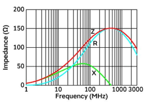
The \(Z\), \(R\), \(X\) plot is the true signature of a ferrite bead.
- \(Z\) (Total Impedance): The overall opposition to current flow (\(Z = \sqrt{R^2 + X^2}\)).
- \(X\) (Reactance): The energy storage part (inductive or capacitive).
- \(R\) (Resistance): The energy loss part that dissipates noise as heat.
The crossover point where the \(R\) curve rises above the \(X\) curve is where the bead starts acting as a proper noise absorber. For effective filtering, you must operate the ferrite bead in its resistive region. For accurate simulation, always use the manufacturer-provided SPICE model4.
What Is Ferrite Bead Saturation?
Your ferrite bead isn't working, even though you chose one with high impedance at the right frequency. The problem might be saturation. Let's explore this hidden performance killer.
Ferrite bead saturation occurs when the DC bias current flowing through the bead is too high. This aligns the magnetic domains in the ferrite core, which drastically reduces its ability to oppose high-frequency currents. Its impedance can drop by over 90%, rendering it useless.
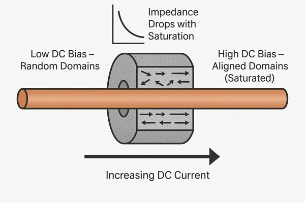
A bead rated for \(600 \Omega \text{ @ } 100 \text{ MHz}\) with no DC bias might drop to just \(50 \Omega\) when a \(500 \text{ mA}\) DC current is applied.
Solutions for High-Current Applications
| Solution | How It Works | Considerations |
|---|---|---|
| Use a Larger Bead | Physically larger beads have more ferrite material and handle more current. | Takes up more PCB space. |
| Parallel Two Beads | Splits the DC current between two beads, reducing the saturation in each. | Takes more space; halves the DCR and total impedance. |
| Switch Filter Type | For very high currents (\(> 5-10 \text{ A}\)), use a discrete LC filter with a large inductor. | Much larger and more complex, but necessary for high power. |
What Are the Different Types of Ferrite Materials?
NiZn or MnZn? Choosing the right ferrite material is crucial for performance at your target frequency. Don't just guess. Understand the difference and when to use each one.
The two most common ferrite materials for beads are Nickel-Zinc (NiZn) and Manganese-Zinc (MnZn). MnZn is best for lower frequencies (typically below \(5 \text{ MHz}\)), while NiZn is ideal for higher frequencies (from \(2 \text{ MHz}\) into the GHz range).
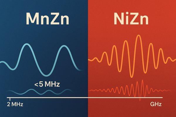
The choice of material determines the bead's optimal frequency range, based on its internal resistivity.
MnZn vs. NiZn Ferrite Materials
| Feature | Manganese-Zinc (MnZn) | Nickel-Zinc (NiZn) |
|---|---|---|
| Frequency Range | Lower Frequencies (\(\approx 100 \text{ kHz} \text{ to } 5 \text{ MHz}\)) | Higher Frequencies (\(\approx 2 \text{ MHz} \text{ to } >1 \text{ GHz}\)) |
| Resistivity | Low (\(\approx 0.1 \text{ to } 10 \text{ } \Omega \cdot \text{m}\)) | High (\(>10,000 \text{ } \Omega \cdot \text{m}\)) |
| Primary Use | Power line filtering, SMPS5 noise, low-frequency EMI. | High-speed data lines, clock lines, RF signal path filtering. |
What Are Alternatives to Using a Ferrite Bead for Noise Suppression?
A ferrite bead isn't always the perfect answer. Sometimes, you need a different tool from your engineering toolbox. Let's look at the alternatives and when they make more sense.
Alternatives to ferrite beads include simple resistors, LC filters for sharper filtering, common-mode chokes for differential signals, and good PCB layout practices. Proper layout, such as grounding and shielding, should always be your first line of defense against noise.
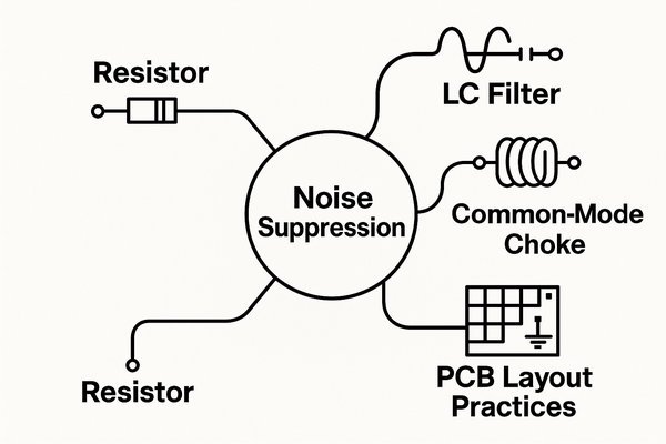
Good PCB layout is a design philosophy, not a component. But when a component is needed, here's how the options compare.
Comparison of Noise Filtering Components
| Component | Best For | Pros | Cons |
|---|---|---|---|
| Ferrite Bead | General purpose high-frequency noise absorption. | Simple, small, effective at dissipating noise. | Subject to saturation; broad (not sharp) filtering. |
| Resistor | Low-speed signal isolation. | Cheapest, simplest, very predictable. | High DC loss (voltage drop); poor filtering performance. |
| LC Filter | Applications needing a sharp frequency cutoff. | Very high attenuation; tunable. | Complex, larger, can cause resonance if not designed properly. |
| Common-Mode Choke6 | Filtering differential pairs (USB, Ethernet, CAN). | Filters noise without distorting the signal. | Larger, more expensive, only works on common-mode noise. |
Conclusion
Ferrite beads are powerful for suppressing high-frequency noise. However, their effectiveness depends entirely on choosing the right one based on frequency, current, and impedance, and understanding their limitations.
-
Learn how a spectrum analyzer helps you identify noise frequencies in your circuit, a crucial first step in effective ferrite bead selection. ↩
-
Learn how DC Resistance (DCR) affects voltage drop and circuit performance, helping you choose the right ferrite bead for your design. ↩
-
Learn how the quality factor (Q) impacts the performance of ferrite beads and inductors, helping you choose the right component for your circuit. ↩
-
Exploring SPICE models can enhance your simulation accuracy and design efficiency. ↩
-
Learn how SMPS (Switched-Mode Power Supply) operates and why it's crucial for efficient power conversion in modern electronic devices. ↩
-
Learn about Common-Mode Chokes and their role in maintaining signal integrity while filtering noise in communication systems. ↩


