 Skip to content
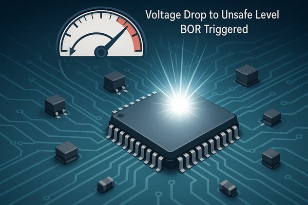
Your microcontroller-based product is locking up randomly in the field. This erratic behavior can corrupt data or brick the device, causing costly recalls. A Brown-Out Reset is your first line of defense.
A Brown-Out Reset (BOR) is a critical safety feature that automatically resets a microcontroller when its supply voltage (\(V_{DD}\)) drops below a pre-defined, safe operating threshold. This prevents unstable code execution and data corruption caused by insufficient power, ensuring the device recovers gracefully.
To build truly reliable products, you have to master the subtle failure modes. A voltage sag is one of the most common yet overlooked causes of system failure. In my nearly 20 years of hardware design, from aerospace to medical devices, I've learned that a correctly implemented BOR is the bedrock of system stability. It's not just a feature to be enabled; it's a parameter to be precisely engineered. It works in concert with your power delivery network, software watchdogs, and overall system architecture to ensure resilience. Let's move beyond the basics and explore the nuances that separate a good design from a great one.
What is the difference between a Brown-Out Reset (BOR) and a Power-On Reset (POR)?
You assume all resets are the same. This leads to designs that fail unexpectedly when the power supply isn't perfect. Knowing how BOR and POR differ is fundamental to reliability.
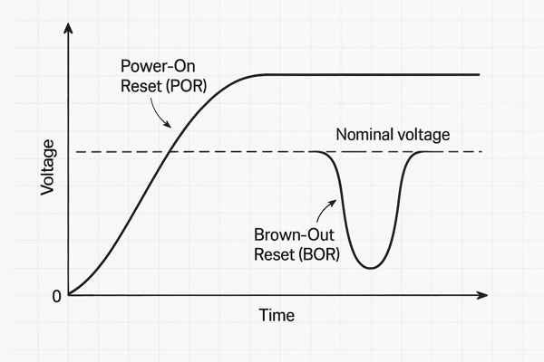
A Power-On Reset (POR) occurs only once when power is first applied, taking the voltage from 0V to its operating level. A Brown-Out Reset (BOR) triggers anytime the voltage dips during operation, protecting the chip from sags without a full power cycle.
The distinction between these two reset types is crucial for diagnosing issues. While they both force the MCU to the reset vector, their internal implementation, timing, and purpose are distinct. I've seen engineers chase software bugs for weeks, only to find the root cause was a noisy power supply causing intermittent BORs—something that could have been diagnosed immediately by understanding these differences.
How do POR and BOR Circuits and Timing Differ?
A POR circuit is designed for a one-time event. It often includes a longer, fixed time delay (e.g., 64 ms) controlled by an internal RC oscillator. This delay ensures not just that \(V_{DD}\) is stable, but also that the main crystal oscillator has had ample time to start up and stabilize before the CPU begins fetching instructions. A BOR, conversely, is designed for speed. Its goal is to react to a sudden voltage drop as quickly as possible to prevent code execution at an unsafe voltage. Its reset duration is typically much shorter—just long enough to reset the internal logic and hold it until the voltage recovers.
POR vs. BOR: A Side-by-Side Comparison
| Feature | Power-On Reset (POR) | Brown-Out Reset (BOR) |
|---|---|---|
| Trigger Condition | \(V_{DD}\) rising from or near 0V. | \(V_{DD}\) falling below a set threshold during operation. |
| Reset Duration | Typically longer, fixed delay (e.g., 16-64 ms) to allow oscillator stabilization. | Shorter, just long enough to ensure a clean reset and recovery. |
| Primary Purpose | Ensure a clean, stable start-up from a power-off state. | Provide rapid protection against transient voltage sags and prevent malfunction. |
| Circuit Focus | Stability and startup sequence integrity. | Speed of detection and reaction. |
What are the advantages of enabling a Brown-Out Reset?
You might disable features like BOR to save a few microamps of power. But this can cause silent data corruption or system lock-ups that are a nightmare to debug later.
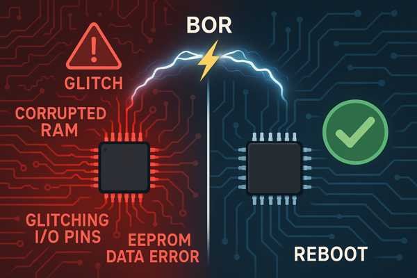
The main advantage is unquestionable system reliability. A BOR prevents the CPU from executing code with insufficient voltage, which can corrupt RAM, write garbage to EEPROM, and drive I/O pins to unpredictable states. It guarantees a controlled restart instead of a chaotic failure.
In my work on high-stakes systems, from Honeywell security panels to Smiths Medical infusion pumps, the BOR is a non-negotiable safety layer. Let's look at the advantages an expert engineer considers.
How Does a BOR Prevent Data Corruption?
This is the most obvious benefit. Writing to non-volatile memory (NVM) like Flash or EEPROM is an atomic operation that must complete fully. A voltage sag during a write cycle can corrupt the memory block, potentially bricking the device. A BOR acts as a preemptive halt, preserving the integrity of your device's firmware and stored user data.
How Does a BOR Maintain a Predictable System State?
Complex firmware relies on state machines. A voltage droop can cause the CPU to fetch a corrupted instruction or operand, throwing the system into an undefined state from which it may never recover. A BOR is the ultimate recovery mechanism, forcing the state machine back to its defined initial state.
Can a BOR Help Safeguard Against Security Glitches?
This is a more advanced consideration. Malicious actors can use precisely timed voltage dips (voltage glitching) as a physical attack vector to bypass security checks or dump protected memory. While a standard BOR isn't a dedicated security feature, a fast-acting, properly configured BOR can sometimes help mitigate these attacks by resetting the device before the glitch can be fully exploited. In security-conscious designs, the BOR is one of several layers in a robust defense-in-depth strategy.
Are there any disadvantages to using a Brown-Out Reset?
You want to enable every safety feature for maximum robustness. But in battery-powered IoT devices where every microamp matters, the BOR's constant power draw becomes a critical design trade-off.
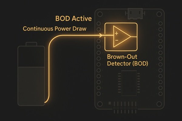
The primary disadvantage is increased power consumption. The Brown-Out Detector (BOD) circuit is an analog comparator that must be active even in low-power sleep modes. This adds a small but continuous current drain that can significantly impact the battery life of a device.
This is a classic engineering trade-off. However, modern MCUs provide more sophisticated ways to manage this.
Why is Power Consumption the Main Disadvantage of a BOR?
For an older MCU like the Microchip ATtiny85, the math is stark. The sleep current might be ~5 µA, but the BOR circuit adds another ~18 µA, increasing standby consumption by nearly five times. This can reduce a projected 5-year battery life to just over one year. For a simple logger, this might be an acceptable trade-off, but for a competitive commercial product, it's a significant drawback.
How Can You Mitigate BOR Power Consumption in Modern MCUs?
Modern microcontrollers offer more granular control. For example, an STM32L4 (low-power series) allows you to configure the BOR to be active in Run and Low-Power Run modes, but automatically disable it in deeper sleep modes like Stop or Standby. Some even offer a separate, ultra-low-power BOR that has a slower response time but consumes only a few hundred nanoamps, providing a baseline level of protection without destroying your power budget.
Here's how the BOR features compare:
| Feature | "Legacy" MCU (e.g., ATtiny85) | Modern Low-Power MCU (e.g., STM32L4) |
|---|---|---|
| BOR Current Draw | High (~18 µA), always on. | Low (~1-3 µA) and mode-dependent. |
| Sleep Mode Behavior | Always active, draining the battery. | Can be configured to disable automatically in deep sleep modes. |
| Configuration | A few fixed voltage levels. | Multiple, granular levels for different power modes. |
| Trade-off | Simple, but inefficient for battery power. | Complex to configure, but highly power-efficient. |
What happens inside a microcontroller during a Brown-Out Reset?
Saying "it just resets" isn't a detailed enough explanation for a professional engineer. If you don't understand the internal sequence of events, you can't effectively design for or debug reset-related issues.
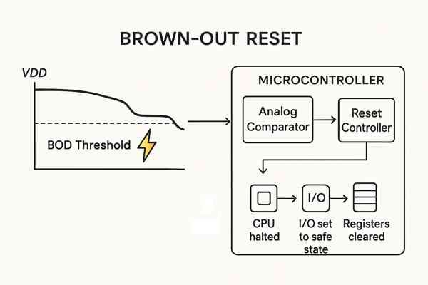
When \(V_{DD}\) drops below the BOD threshold, an internal analog comparator alerts the reset controller. The controller immediately halts the CPU clock, forces I/O pins to a safe state, and clears internal registers to their default values, preparing for a clean restart.
This hardware-based sequence is critical, but what happens after the reset is what separates basic and expert-level debugging.
What is the Step-by-Step Hardware Sequence of a BOR Event?
- Voltage Drop: The system's supply voltage, \(V_{DD}\), falls.
- Comparator Trigger: An internal analog comparator, using a stable bandgap reference, detects that \(V_{DD}\) has crossed the \(V_{BOR}\) threshold.
- Reset Assertion: The comparator's output asserts an internal
RESETsignal to the system's reset controller. - System Halt & Reset: The reset controller gates the system clock, halts the CPU, and forces all internal registers (peripherals, SFRs, Program Counter) to their default power-on values.
- Restart Sequence: The
RESETsignal is held until \(V_{DD}\) rises above the BOR threshold plus hysteresis. The MCU then begins its startup sequence from the reset vector (0x0000).
How Can You Identify the Cause of a Reset Using Registers?
Here's the crucial part for diagnostics. Nearly every modern MCU has a Reset Control/Status Register (e.g., RCC_CSR on an STM32, RSTFLR on an AVR). This register contains flags that tell you why the last reset occurred. Was it a Power-On Reset? An external pin reset? A watchdog timer? Or a Brown-Out Reset? As an expert, your startup code should always read this register immediately, log its value to a variable, and then clear the flags. You can then save this reset reason to EEPROM or transmit it over a serial port. When a customer says "the device just randomly reboots," this log is your single most valuable piece of data. It instantly tells you if you have a software problem (watchdog reset) or a hardware/power supply problem (brown-out reset).
What is a Brown-Out Detector (BOD) voltage level?
You know you need to set a BOR threshold. But selecting a random value from the datasheet without understanding its context can cause as many problems as it solves.
The BOD voltage level, or \(V_{BOR}\), is the specific voltage threshold below which the microcontroller initiates a reset. Modern MCUs offer several selectable levels, typically ranging from 1.8V to 4.5V, allowing you to match the reset point to your system's specific power requirements.
The choice of level is a critical design parameter that directly impacts system robustness.
What Are the BOR Voltage Levels on an ATmega328P?
For a common MCU like the Microchip ATmega328P, the options are straightforward, as shown in the table below. For a 5V system, the 4.3V level is a safe choice.
BODLEVEL Fuse Bits | Typical Brown-out Trigger Voltage (\(V_{BOT}\)) | Recommended \(V_{CC}\) Range |
|---|---|---|
111 | Disabled | N/A |
110 | 1.8V | 2.7V - 5.5V |
101 | 2.7V | 4.0V - 5.5V |
100 | 4.3V | 4.5V - 5.5V |
Why is Understanding BOR Datasheet Tolerances Important?
For a high-reliability product, the "Typical" value is not enough. You must look for the Min/Max specifications for \(V_{BOT}\) in the electrical characteristics table. A level with a "typical" value of 2.7V might have a range of 2.55V to 2.85V over temperature and process variations. Your worst-case analysis must use these Min/Max values to guarantee performance under all conditions. Relying on the typical value is a common mistake that can lead to failures at temperature extremes.
What is voltage-level hysteresis in a Brown-Out Detector?
Your circuit is stuck in a loop, resetting over and over again. This "chatter" can happen if your supply voltage is noisy and hovers right at the reset threshold. Hysteresis is the built-in feature designed to prevent this exact problem.
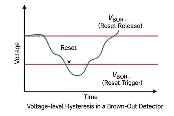
Hysteresis in a BOD circuit creates two distinct thresholds: a falling voltage level to trigger the reset (\(V_{BOR-}\)) and a slightly higher rising voltage level to release it (\(V_{BOR+}\)). This gap prevents the MCU from rapidly oscillating between active and reset states.
This is a fundamental concept in comparator design, applied here for system stability.
How Does Hysteresis Create a "Dead Zone" to Prevent Reset Chatter?
Hysteresis creates a "dead zone" that breaks the reset loop. For example, the BOR might trigger when the voltage falls below 2.70V. But it will only be released once the voltage recovers and rises above 2.85V. That 150mV difference is the hysteresis (\(V_{HYST}\)), a value typically specified in the datasheet (e.g., 150mV for a TI MSP430).
What is the Trade-Off in Selecting a Hysteresis Value?
While essential, the amount of hysteresis presents a trade-off. Your choice depends on the expected noise level and power source characteristics of your system.
| Hysteresis Level | Pros | Cons | Best Use Case |
|---|---|---|---|
| Low (~50mV) | More precise reset window. Faster restart on recovery. | More susceptible to high-frequency noise causing chatter. | Clean, well-regulated power systems with minimal noise. |
| High (~300mV) | Excellent noise immunity. Very stable. | Requires voltage to recover to a higher level, potentially delaying restart. | Noisy environments (e.g., industrial motor control) or systems with slow-recovering power supplies. |
How can the appropriate BOR voltage threshold be selected for a given design?
Choosing a BOR threshold feels like a guess. But if you guess wrong, you can either trigger nuisance resets during normal operation or, worse, fail to trigger a reset when the MCU is about to malfunction.
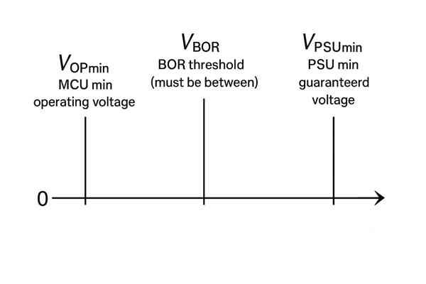
The rule is simple: select a BOR threshold (\(V_{BOR}\)) that is above your microcontroller's minimum operating voltage (\(V_{OP_{min}}\)) for its clock speed, but below your power supply's lowest guaranteed output voltage (\(V_{PSU_{min}}\)).
A truly professional analysis goes one step deeper to account for dynamic conditions. The following steps and summary table illustrate this expert-level approach.
How Do You Determine the MCU's Minimum Operating Voltage?
First, check the MCU's datasheet for the "voltage vs. frequency" graph. Find the minimum voltage required for your maximum operating frequency across the full temperature range. Let's say this is 2.5V. This is your absolute minimum operating voltage, \(V_{OP_{min}}\).
How Do You Calculate the Power Supply's Worst-Case Output?
Next, analyze your voltage regulator's datasheet. Account for its initial accuracy (e.g., ±1%), output voltage change over temperature, and change due to load regulation. Summing these up might give you a worst-case static output of 3.20V for a 3.3V regulator. This is your static \(V_{PSU_{min}}\).
Why Must You Account for Dynamic Voltage Drop (Vdroop)?
This is the expert step. When a high-current peripheral turns on (like a radio), the voltage will dip momentarily due to the impedance of your Power Delivery Network (PDN). This is called transient response1 or Vdroop. If your static minimum is 3.20V, but a load step causes a 300mV droop, your true minimum voltage is 2.90V.
The final calculation and a summary of our example are below:
| Parameter | Description | Example Value |
|---|---|---|
| \(V_{OP_{min}}\) | MCU absolute minimum operating voltage. | 2.50 V |
| \(V_{PSU_{min}}\) | Regulator's worst-case static minimum output. | 3.20 V |
| \(V_{droop}\) | Max voltage dip during a transient load. | 0.30 V |
| Safe Floor | The lowest voltage during operation (\(V_{PSU_{min}} - V_{droop}\)). | 2.90 V |
| Safe Range | The valid window for the BOR threshold (\(V_{OP_{min}}\) to Safe Floor). | 2.50 V to 2.90 V |
| \(V_{BOR}\) Selected | A practical BOR level chosen from the MCU's options. | 2.70 V |
How can the Brown-Out Reset be configured on a specific microcontroller?
You've done the calculations and selected the perfect BOR level. But this isn't a software setting you can change in your main() function. How do you permanently program this into the chip?
You configure the Brown-Out Reset by programming special, non-volatile memory bits inside the microcontroller. These are commonly called fuse bits (on Microchip/AVR MCUs) or option bytes (on STMicroelectronics/ARM MCUs), and they are set using a dedicated hardware programmer.

This is a manufacturing step, and getting it right is critical.
How is a BOR Configured on Different MCU Platforms?
- AVR (e.g., ATmega328P): Configuration is done by writing to the "extended fuse byte" using a tool like
avrdudeand an ISP programmer. It's a low-level, permanent setting. - STM32 (e.g., STM32F4): Configuration is more user-friendly, using a GUI tool like STM32CubeProgrammer to set the
BOR_LEVin the Option Bytes.
Why is Verifying the BOR Configuration During Production Essential?
Here's a tip born from hard experience: your production test jig must include a step to read back and verify the option bytes of every single programmed MCU. I once debugged an issue where an entire batch of 10,000 units was shipped with the BOR disabled because the manufacturing line's programming script was faulty. A simple verification step would have caught it instantly. Don't just program; verify.
How can a power supply circuit be designed to prevent brown-outs?
Your MCU keeps resetting because of brown-outs. This is a clear signal that your power supply circuit is not robust enough for your application's load demands. A better BOR setting won't fix a bad power supply.
To prevent brown-outs, you need a holistic approach to Power Delivery Network (PDN) design: use a hierarchy of capacitors, choose a regulator for its dynamic performance, and implement a low-impedance PCB layout.
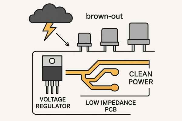
A robust PDN is the best way to prevent voltage sags.
How Does Capacitor Selection (ESR/ESL) Affect PDN Performance?
It's not just about capacitance value. You need a hierarchy:
- Bulk Capacitance (10-100µF): An electrolytic or tantalum capacitor at the regulator output acts as a local energy reservoir for low-frequency, high-current demands.
- Decoupling Capacitance (0.1-1µF): Low-ESR (Equivalent Series Resistance) ceramic capacitors placed as close as possible to each MCU power pin supply high-frequency switching currents.
- High-Frequency Decoupling (1-10nF): A smaller capacitor can sometimes be placed alongside the 0.1µF cap to provide an even lower impedance path for very high-frequency noise.
What are the Best Practices for Power Plane Design?
"Wide traces" is beginner advice. For high-performance MCUs, use a solid, uninterrupted ground plane directly under your components. Use a power plane instead of traces for VDD where possible. This creates a low-impedance path that minimizes Vdroop during transient events. Follow component placement guidelines to ensure the path from the decoupling caps to the MCU pins is short and direct, minimizing parasitic inductance (ESL).
When Should You Use an External Voltage Supervisor?
While internal BORs are good, external voltage supervisors (like a TI TLV809 or Analog Devices ADM809) offer superior performance and features. Use an external part when your design demands it.
| Feature | Internal BOR | External Supervisor IC |
|---|---|---|
| Voltage Accuracy | Wider tolerance (e.g., ±5% to ±10%). | High precision (e.g., ±0.5% to ±2.5%). |
| Quiescent Current | Can be high (1-20µA); varies by MCU. | Can be very low (<1µA for modern parts). |
| Reset Timeout | Fixed or limited options. | Often adjustable with an external capacitor. |
| Temperature Stability | Can drift significantly over temperature. | Very stable over the full industrial temp range. |
| Additional Features | Basic reset function only. | Can include watchdog timers2, manual reset inputs, multiple voltage monitoring. |
| Best For | Cost-sensitive applications with wide voltage margins. | High-reliability, safety-critical, or low-power applications. |
Conclusion
The Brown-Out Reset is a cornerstone of system reliability. Moving beyond the basics means treating it not as a checkbox, but as an engineered parameter in a complete system-level strategy.


