Struggling to quickly pick a resistor for a status LED on your board? You don't want to blow it up, but you also need it to be bright enough to see.
For quick debugging with a \(5\text{V}\) supply, a \(330\Omega\) resistor is a great choice. For a \(3.3\text{V}\) supply, start with \(220\Omega\). These values typically provide a safe current of \(5-15\text{mA}\), which is bright enough for most common red, green, or yellow LEDs without risking damage.
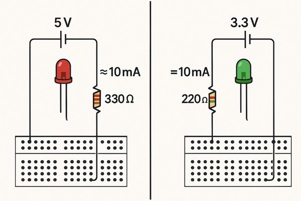
These "rules of thumb" are lifesavers when you're focused on debugging a complex part of your circuit and just need a quick visual indicator. I've relied on them for years, from initial bring-up on a new photonic computing board to quick mods on an infusion pump prototype. But a true professional knows why these values work and how to calculate the perfect one when it matters. Let's dive deeper into the fundamentals, so you can move from guessing to engineering with confidence.
Why Does an LED Need a Current-Limiting Resistor?
You connect an LED directly to your power rail. It flashes brilliantly for a second and then goes dark forever. We've all been there. What happened?
An LED needs a current-limiting resistor because it has very low internal resistance. Without a resistor, it would draw a massive amount of current from the power supply, far exceeding its maximum rating and destroying it almost instantly. The resistor controls the current to a safe level.
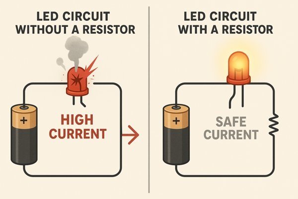
An LED is a diode, and its behavior is very different from a simple resistor. Understanding this is key to using them correctly and avoiding what I call "unscheduled thermal events" on the lab bench.
Understanding the LED's Exponential I-V Curve
Unlike a resistor, an LED has a non-linear current-voltage (\(I-V\)) relationship. Below a certain voltage (its forward voltage, or \(V_{f}\)), almost no current flows. But once you exceed the \(V_{f}\), the current rises exponentially. Once conducting, an LED has a very low dynamic resistance (often just a few ohms), which is why it behaves almost like a short circuit. The external resistor you add becomes the primary factor limiting the current in the loop, keeping it at a safe and predictable level.
Protecting Both the LED and the Driver Circuit
During my time at Honeywell, I was mentoring a junior engineer on the Tuxedo Keypad project. He connected an LED directly to a microcontroller's GPIO pin to check its state. He fried not only the LED but also the GPIO pin itself. This is because the microcontroller tried to supply the massive current the LED was demanding, far exceeding the pin's absolute maximum rating of \(25\text{mA}\). The resistor, therefore, serves two purposes: it protects the LED from overcurrent, and it protects the component that is driving the LED, whether that's an MCU, an op-amp, or a dedicated logic gate.
What is the typical Forward Voltage (Vf) of a Red/Green/Blue LED?
You can't calculate the right resistor value without knowing the LED's forward voltage. Using the wrong value can lead to inaccurate calculations and unexpected brightness levels.
An LED's forward voltage (\(V_{f}\)) depends on its color. Typically, red LEDs are around \(1.8\text{V}\) to \(2.2\text{V}\), green is \(2.0\text{V}\) to \(3.3\text{V}\), and blue or white LEDs are higher, from \(3.0\text{V}\) to \(3.6\text{V}\). Always check the datasheet for the specific part you are using.
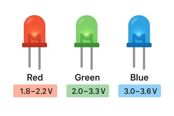
Forward voltage is a fundamental characteristic, but it's not a perfectly fixed number. Several factors can influence it.
Factors that Influence an LED's Forward Voltage
For high-precision designs, you must be aware of these variables, which are summarized in the table below.
| Factor | Typical Effect on \(V_{f}\) | Engineering Consideration |
|---|---|---|
| Temperature | Decreases as temperature increases (approx. \(-2\text{mV}/^{\circ}\text{C}\)) | Designs for wide temperature ranges must account for this shift. |
| Forward Current | Increases slightly as current increases | The change is usually small but can be seen on datasheet graphs. |
| Manufacturing Variation | Varies between devices, even in the same batch | For uniform brightness, order "binned" LEDs with a tight \(V_{f}\) range. |
Table of Typical Forward Voltage by Color
The manufacturer's datasheet is the only true source, but this table provides a reliable starting point for initial designs.
| LED Color | Typical Forward Voltage (\(V_{f}\)) |
|---|---|
| Infrared | \(1.2\text{V} - 1.6\text{V}\) |
| Red | \(1.8\text{V} - 2.2\text{V}\) |
| Amber/Yellow | \(2.0\text{V} - 2.2\text{V}\) |
| Green | \(2.0\text{V} - 3.3\text{V}\) |
| Blue/White | \(3.0\text{V} - 3.6\text{V}\) |
How much current is safe for a standard LED?
You want your indicator to be visible, but you don't want to shorten its lifespan or burn it out. So, how much current is the right amount?
Most standard through-hole (3mm, 5mm) and surface-mount (0603, 0805) LEDs have an absolute maximum continuous forward current of \(20\text{mA}\). For general-purpose indicators, a current of \(5\text{mA}\) to \(10\text{mA}\) is a safe and effective choice that provides good brightness without stressing the component.
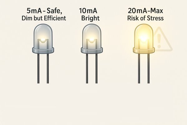
The current you choose is a trade-off between brightness, power consumption, and long-term reliability.
Understanding LED Current Ratings from a Datasheet
This table breaks down the key current specifications you'll find on a datasheet.
| Rating Parameter | Symbol | Typical Value | Description & Usage |
|---|---|---|---|
| Absolute Maximum Continuous Current | \(I_{F,max}\) | \(20 - 30\text{mA}\) | The "do not exceed" value. Exceeding it can cause permanent damage. |
| Typical Forward Current | \(I_{F}\) | \(10 - 20\text{mA}\) | The current at which specs like brightness and \(V_{f}\) are measured. |
| Pulsed Forward Current | \(I_{FP}\) | \(>100\text{mA}\) | Higher current allowed for very short pulses (e.g., in multiplexing). |
Choosing an LED Current Level for Your Application
Not every indicator needs to be blindingly bright. For battery-powered devices, every milliamp counts.
| Application | Recommended Current | Rationale |
|---|---|---|
| Low Power / Battery Life | \(1 - 3\text{mA}\) | Visible in most indoor settings, drastically extends battery life. |
| Standard Status Indicator | \(5 - 10\text{mA}\) | Good balance of brightness, power consumption, and long lifespan. |
| High Brightness / Outdoor | \(15 - 20\text{mA}\) | Pushing the LED for maximum visibility, at the cost of efficiency and lifespan. |
What is a Good Rule-of-Thumb Resistor Value for an LED?
You're at your lab bench, probing a circuit, and you just need a quick indicator. You don't have time to look up datasheets and do calculations. What do you grab?
For a \(5\text{V}\) supply, a \(330\Omega\) resistor is a universal choice. For a \(3.3\text{V}\) supply, a \(220\Omega\) resistor works well for most LEDs. These values are safe, effective, and commonly found in any electronics lab.
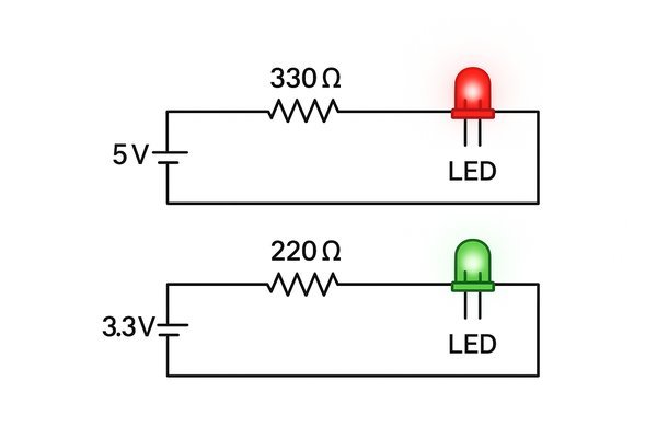
Quick Reference Table for Rule-of-Thumb Resistors
This summary table makes the rules easy to remember.
| Supply Voltage (\(V_{S}\)) | Rule-of-Thumb Resistor | Approx. Current (for a \(2\text{V}\) LED) | Common SMD Code |
|---|---|---|---|
| \(5.0\text{V}\) | \(330\Omega\) | \(\approx 9\text{mA}\) | 331 |
| \(3.3\text{V}\) | \(220\Omega\) | \(\approx 6\text{mA}\) | 221 |
How to Calculate the Value for an LED Resistor?
The rule of thumb is great for debugging, but for a final product design, you need precision. Calculating the exact resistor value is a fundamental skill.
To calculate the required resistance, use Ohm's Law. The formula is: \(R = (V_{S} - V_{f}) / I_{f}\). You need three values: the supply voltage (\(V_{S}\)), the LED's forward voltage (\(V_{f}\)), and your desired forward current (\(I_{f}\)).
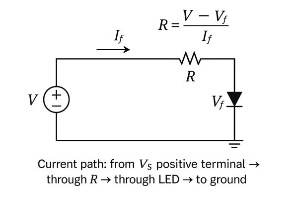
A simple calculation is good, but a professional design requires a more robust approach.
Step 1: Find Specs in the LED Datasheet
First, get the key parameters from the component datasheet and your system requirements.
- Supply Voltage (\(V_{S}\)): Know your rail's nominal voltage and tolerance (e.g., \(5\text{V} \pm 5\%\)).
- LED Forward Voltage (\(V_{f}\)): Find the min, typical, and max values in the datasheet.
- Desired Forward Current (\(I_{f}\)): Choose your target current (e.g., \(10\text{mA}\)).
Step 2: Calculate Resistance Using Ohm's Law
Let's calculate for a typical case first: \(V_{S} = 5\text{V}\), \(V_{f} = 2.1\text{V}\), \(I_{f} = 0.010\text{A}\).
\(R = (5\text{V} - 2.1\text{V}) / 0.010\text{A} = 290\Omega\).
The nearest standard E24 value is \(300\Omega\).
Step 3: Perform a Worst-Case Analysis for Reliability
For a robust design, you must ensure the current is safe under all conditions. This table compares the parameters used for a simple "typical" calculation versus a professional "worst-case" analysis.
| Parameter | Typical Calculation Value | Worst-Case Calculation Value (for max current) |
|---|---|---|
| Supply Voltage (\(V_{S}\)) | Nominal (e.g., \(5.0\text{V}\)) | Maximum possible value (e.g., \(5.0\text{V} + 5\% = 5.25\text{V}\)) |
| Forward Voltage (\(V_{f}\)) | Typical value from datasheet | Minimum possible value from datasheet (e.g., \(V_{f,min}\)) |
| Resistor Value (\(R\)) | Chosen standard value (e.g., \(300\Omega\)) | Minimum possible value (e.g., \(300\Omega - 5\% = 285\Omega\)) |
LED Resistor Selection Guide for 5V and 3.3V Supplies
Here is a comprehensive table to help you select an appropriate E24 series resistor for common LEDs and supply voltages, targeting a safe and visible current.
| LED Color | Typical \(V_{f}\) | Recommended Resistor (\(5\text{V}\) Supply) | Approx. Current (\(5\text{V}\)) | Recommended Resistor (\(3.3\text{V}\) Supply) | Approx. Current (\(3.3\text{V}\)) |
|---|---|---|---|---|---|
| Red | \(2.0\text{V}\) | \(300\Omega\) | \(10.0\text{mA}\) | \(130\Omega\) | \(10.0\text{mA}\) |
| Yellow | \(2.1\text{V}\) | \(300\Omega\) | \(9.7\text{mA}\) | \(120\Omega\) | \(10.0\text{mA}\) |
| Green | \(2.2\text{V}\) | \(270\Omega\) | \(10.4\text{mA}\) | \(110\Omega\) | \(10.0\text{mA}\) |
| Blue/White | \(3.2\text{V}\) | \(180\Omega\) | \(10.0\text{mA}\) | \(10\Omega\) (Use with caution) | \(10.0\text{mA}\) (Unstable) |
As noted, using a simple resistor for blue or white LEDs on a \(3.3\text{V}\) rail is risky due to the low voltage headroom. A dedicated constant-current driver is a much more robust solution in that specific case.
What Power Rating (Wattage) Resistor is Needed for an LED?
You've calculated the resistance, but what about the power rating? Choosing a resistor with too low a power rating can lead to it overheating and failing.
For almost all standard LED indicator circuits, the lowest standard power rating, such as \(1/8\text{W}\) (\(0.125\text{W}\)) for through-hole, or 0603/0402 sizes for SMD, is perfectly sufficient.
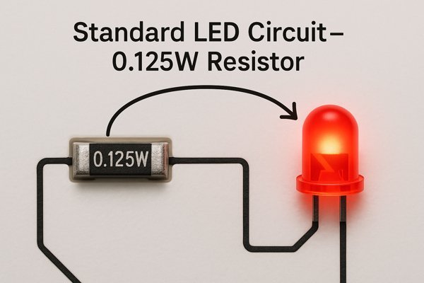
Calculating the Resistor's Power Dissipation
The formula is \(P = I^{2} \times R\). Let's use our \(5\text{V}\) green LED example: Current is \(\approx 9.7\text{mA}\) (\(0.0097\text{A}\)) with a \(300\Omega\) resistor.
\(P = (0.0097\text{A})^{2} \times 300\Omega \approx 0.028\text{W}\), or \(28\) milliwatts. A standard professional practice is to derate components by 50%, meaning you should select a part rated for at least \(2 \times 28\text{mW} = 56\text{mW}\).
Choosing a Resistor Package Based on Power Rating
This table shows the power handling capabilities of common resistor packages.
| Resistor Package | Typical Power Rating (Watts) | Max Power (mW) |
|---|---|---|
| 0402 SMD | \(1/16 \text{ W}\) | \(62.5 \text{ mW}\) |
| 0603 SMD | \(1/10 \text{ W}\) | \(100 \text{ mW}\) |
| 0805 SMD | \(1/8 \text{ W}\) | \(125 \text{ mW}\) |
| 1/4W Through-Hole | \(1/4 \text{ W}\) | \(250 \text{ mW}\) |
Since our calculated power dissipation is well under \(62.5\text{mW}\), even the smallest common 0402 package is sufficient.
Does it Matter if the Resistor is on the Anode or Cathode Side of the LED?
You're laying out your PCB and wondering about the optimal placement of the resistor. Does it need to go before or after the LED in the circuit?
For a simple circuit powered by a DC source, it makes no difference. Whether the resistor is connected to the anode or the cathode, it will limit the current in the series circuit just the same.
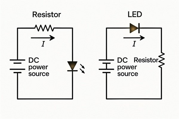
Comparing Resistor Placement in Different Circuits
While placement is flexible in basic circuits, it becomes critical in more advanced designs.
| Circuit Topology | Recommended Resistor Placement | Reason |
|---|---|---|
| Simple DC Circuit | Either side (Anode or Cathode) | Current is the same everywhere in a simple series loop. |
| Low-Side NPN Switch | High Side (\(VCC\) to Anode) | Standard convention; separates the switching and limiting functions. |
| Constant-Current Sink | Low Side (Cathode to GND) | The resistor acts as a current sense element providing feedback. |
What Happens if the Resistor Value for an LED is Too High or Too Low?
Choosing the wrong resistor value isn't just about brightness. It can lead to component failure or a circuit that doesn't work as intended.
If the resistor value is too low, the current will be too high, potentially burning out the LED. If the resistor value is too high, the current will be too low, making the LED dim or preventing it from lighting up at all.
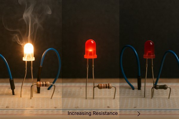
The Risk of Using a Resistor Value That Is Too Low
A resistor that is too small creates a low-resistance path, causing current to spike. This generates intense heat in the LED's semiconductor junction, quickly causing irreversible damage—what we call "letting the magic smoke out." It can also over-stress and damage the driving component, like a microcontroller's GPIO pin.
The Problem with Using a Resistor Value That Is Too High
A resistor with too much resistance will severely limit the current. Since an LED's brightness is proportional to the forward current, this will result in a dim LED. If the resistance is so high that the voltage drop across it leaves less than the required forward voltage (\(V_{f}\)) for the LED, the LED will not turn on at all.
How to Connect Multiple LEDs to One Power Source?
You need to light up a row of status indicators on your front panel. What's the best way to wire them all to the same \(5\text{V}\) supply?
The most reliable method is to connect each LED in parallel, with each one having its own dedicated current-limiting resistor. Connecting LEDs in series is also possible but requires a high enough supply voltage and is less robust.
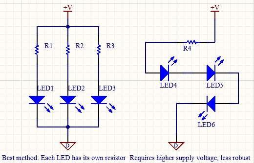
The Professional Method: Parallel Wiring with Individual Resistors
This is the professional standard. Each LED gets its own resistor, which connects to the main power rail. This guarantees that each LED receives its intended current, ensuring uniform brightness and long-term reliability. If one LED fails, the others are unaffected.
The Alternative Method: Series Wiring with a Single Resistor
Connecting LEDs in series is efficient (only one resistor) but has two major drawbacks. First, the supply voltage must exceed the sum of all the \(V_{f}\) values. Second, if one LED fails open, the entire string goes out, creating a single point of failure.
The Incorrect Method: Parallel Wiring with a Single Resistor
Never connect multiple LEDs in parallel with a single shared resistor. Due to tiny manufacturing variations, the LED with the lowest \(V_{f}\) will draw the most current, leading to thermal runaway and eventual failure.
Summary Table of Multiple-LED Wiring Methods
| Method | Pros | Cons |
|---|---|---|
| Parallel (Individual Resistors) | Reliable, consistent brightness. | Higher component count. |
| Series (Single Resistor) | Low component count. | Requires high supply voltage; single point of failure (if one LED breaks, all go out). |
| Parallel (Single Resistor) - WRONG | (None) | Unreliable, inconsistent brightness, leads to thermal runaway and LED failure. |
Conclusion
Choosing the right current-limiting resistor is essential. For quick bench work, \(330\Omega\) (\(5\text{V}\)) and \(220\Omega\) (\(3.3\text{V}\)) are reliable. For production, always calculate using datasheet values and perform a worst-case analysis to ensure your product is robust and reliable for years to come.


