 Skip to content
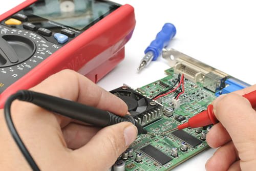
⚠️ PCB failures can be devastating, causing costly delays and frustrating repairs. Engineers struggle with hidden defects and complex layouts, making troubleshooting feel like guesswork. Without a structured approach, diagnosing short circuits and open traces is nearly impossible. This guide provides a clear, step-by-step method using a multimeter to quickly pinpoint and fix PCB faults.
To test a PCB board with a multimeter, start with a visual inspection for damage. Use continuity mode to check open circuits—no beep means a break. Measure resistance between power and ground; low resistance suggests a short. Power the PCB and verify voltages at key points.If the issue persists, test on components like functional ICs, resistors, capacitors and diodes.
Now that you understand the basics, let’s explore step-by-step PCB troubleshooting, covering short detection, open circuits, bad solder joints, and component failures, ensuring your PCB works flawlessly.
How to Check If a PCB is Working?
To determine if a PCB is functional, follow these steps in the correct order:
Step 1: Identify the Power Type (Power OFF)
- Determine whether the PCB operates on AC or DC power by referring to the circuit design, silkscreen labels, or datasheets.
- This step ensures that you use the correct voltage settings on the multimeter.
Step 2: Test the Power and Ground Connections for Continuity (Power OFF)
- Set the multimeter to continuity mode (beeping mode).
- Place one probe on the power input (e.g., VIN, VCC, or a designated power pad) and the other on key power distribution points (e.g., voltage regulator input, power plane via, or component power pin).
- A beep confirms a continuous power path.
- Repeat this process for ground connections to ensure all GND points are properly connected.
- If there’s no beep, there may be a broken trace, faulty via, or internal layer issue affecting power distribution.
Step 3: Check for Short Circuits (Power OFF)
- Set the multimeter to resistance mode (ohms) or continuity mode.
- Place the black probe on ground (GND) and the red probe on the power rail (e.g., VCC, 3.3V, 5V, 12V).
- A low resistance reading (close to 0Ω) or a beep in continuity mode indicates a short circuit.
- If a short is detected, inspect solder joints, components, and traces for possible faults before proceeding.
Step 4: Set the Multimeter to the Correct Voltage Mode (Power OFF)
- If the PCB uses DC power, set the multimeter to DC voltage mode.
- If the PCB uses AC power, set the multimeter to AC voltage mode.
Step 5: Check the Voltage Reading (Power ON)
- Turn ON the power supply.
- Place the black probe on a ground point (GND) and the red probe on the power input or a key power rail (e.g., VCC, 3.3V, 5V, or 12V rail depending on the PCB design).
- Compare the voltage reading with the expected value. Deviations may indicate a power regulation issue or component failure.
Step 6: Inspect Indicator LEDs or Display Outputs (Power ON)
- Some PCBs have power indicator LEDs that light up when powered correctly.
- If the board has display outputs or status indicators, check whether they function as expected.
How Do You Know If a PCB Board is Bad?
A faulty PCB may exhibit several signs of failure, including:
- Overheating or Burnt Marks – Excessive heat or burnt areas on the PCB could indicate short circuits, overcurrent conditions, or component failure.
- Malfunctioning or Non-Responsive Components – If components like LEDs, ICs, or displays fail to work correctly, it could suggest broken traces, solder joint issues, or component damage.
- Frequent Circuit Shorts or Open Circuits – Short circuits or open circuits between traces or components can lead to system instability, power loss, or total failure.
- Visible Physical Damage or Corrosion – Physical defects like cracked solder joints, damaged pads, or corrosion can affect the PCB’s electrical performance and reliability.
- Intermittent or Total Power Loss – Sudden power drops or frequent power failures can signal broken power traces, faulty components, or issues with the power supply.
- Unexpected Behavior Under Load - When the PCB works fine without load but fails or behaves erratically under load, it might indicate power delivery issues, poor trace routing, or design flaws in the PCB. This behavior is common in high-frequency or high-power circuits.
- Noisy or Distorted Signals - In more complex designs, distorted or noisy signals can indicate that the PCB has issues like improper grounding, poor shielding, or trace interference. These are often signs of PCB layout problems that can compromise performance.
- Failing to Pass Burn-in Testing - For high-performance PCBs, burn-in testing is essential to ensure the board can handle extended use under real-world conditions. If the PCB fails this test, it could be due to component stress or thermal issues resulting from poor design or manufacturing.
If you notice any of these issues, further testing is required to identify the root cause and prevent future failures.
Which Method is Used for PCB Board Testing?
There are several methods for testing a PCB board to ensure it functions correctly, depending on its complexity and stage of production.
Visual Inspection
- Purpose: Checks for visible defects like soldering issues, cracks, burn marks, and misplaced components. Visual inspection helps identify problems that could cause electrical issues or physical damage to the PCB.
- Tools Used: Magnifying tools or automated optical inspection (AOI) machines to inspect the solder joints, component placement, and board condition.
- When to Use: Primarily during initial stages of assembly or before further testing, to detect basic manufacturing defects.
Continuity Testing
- Purpose: Verifies electrical continuity between points on the PCB to ensure that traces and connections are intact and there are no open circuits. This method helps in detecting broken traces or unintended disconnections on the board.
- Tools Used: A multimeter set to continuity mode, which emits a sound when there is a continuous connection.
- When to Use: Typically used after assembly to check power and ground traces or critical signal paths for any breakages.
In-Circuit Testing (ICT)
- Purpose: Checks the functionality of individual components and their connections on the PCB, ensuring proper placement and operation. ICT helps identify faulty components such as resistors, capacitors, or transistors that are not functioning correctly.
- Tools Used: ICT fixture, test probes, and testing machine that applies voltage and current to components to check their behavior against expected results.
- When to Use: Used in complex or high-density boards after assembly to verify the functionality of individual components and connections.
Functional Circuit Testing (FCT)
- Purpose: Verifies the overall PCB functionality by simulating real-world operating conditions, ensuring the PCB operates as intended within the complete system. FCT checks the board’s performance when all components are powered and working together.
- Tools Used: FCT fixture to interface with the PCB, power supplies, and other specialized test equipment for real-world simulation.
- When to Use: Performed after assembly, before deployment, to ensure the PCB functions correctly under normal operational conditions.
X-ray Inspection
- Purpose: Detects hidden defects inside multi-layer PCBs or BGA (Ball Grid Array) packages. X-ray inspection is crucial for identifying problems like undetected soldering issues, misalignment of components, or internal short circuits that are not visible on the surface.
- Tools Used: X-ray machines equipped with high-resolution imaging systems for detailed cross-sectional views of the PCB and components.
- When to Use: For complex boards or when inspecting BGA solder joints for troubleshooting.
Choosing the appropriate testing method for your PCB ensures that the board performs as expected and meets quality standards. Visual inspection, continuity testing, ICT, Functional Circuit Testing (FCT),and X-ray inspection are critical methods used to verify the functionality, quality, and durability of the PCB.
How to Test a Circuit Board for a Short?
Testing for short circuits on a PCB is crucial for identifying faulty connections that could lead to power loss or permanent damage. Here's a professional approach to testing for shorts:
Steps to Test for Short Circuits:
- Power Off the PCB: Before you begin testing, ensure the PCB is powered off to avoid causing further damage to sensitive components.
- Set the Multimeter to Continuity or Resistance Mode: In continuity mode, your multimeter will beep when there is a direct connection (short) between points. In resistance mode, a short circuit will show a very low resistance (close to 0 ohms).
- Test Between Power and Ground: First, check the points between the power rails and ground traces. A short between these two will cause power issues and could damage the board.
- Check Between Adjacent Components or Traces: After verifying the power and ground, check for shorts between adjacent components or traces. This will help detect any unintended connections or solder bridges.
- Test Specific Components: If you suspect certain components might be causing the short, use the multimeter to test them individually (e.g., capacitors, diodes, resistors) for unusual resistance values.
Key Things to Look Out For:
- Low Resistance Readings: A low resistance (near 0 ohms) indicates a short circuit.
- Beeping in Continuity Mode: If the multimeter beeps when testing two points that should not be connected, it’s a clear indication of a short.
If you find any shorts, carefully inspect the PCB for solder bridges, damaged traces, or misplaced components. These can be repaired to restore the functionality of the board.
How to Find a Short to Ground on a PCB?
Finding a short to ground on a PCB is essential for diagnosing issues related to power loss or board malfunction. A short to ground happens when a trace or component unintentionally connects to the ground, causing excessive current flow or voltage irregularities. Here's how to identify this problem:
Steps to Find a Short to Ground:
- Power Off the PCB: Always start with the board powered off to avoid electrical hazards or further damage.
- Set the Multimeter to Continuity or Resistance Mode: In continuity mode, your multimeter will emit a sound if there's a direct connection to ground. In resistance mode, you’ll measure low resistance, indicating a short.
- Inspect for Physical Damage or Solder Bridges: Before testing individual components, visually check the PCB for damaged traces, solder bridges, or corrosion that could cause an unintended path to ground. These issues are often visible and can be easily fixed.
- Test Between Power Rails and Ground: After checking for visible damage, test between the power rails (like VCC or other voltage supply pins) and ground. A short to ground will show low resistance (almost 0 ohms) or a beep in continuity mode.
- Check Individual Components: After confirming there's no visible damage, test each component’s leads (e.g., transistors, capacitors, and resistors) to see if any show continuity to ground where they shouldn’t.
Common Indicators of Short to Ground:
- Low Resistance: A resistance value close to 0 ohms indicates a short circuit to ground.
- Multimeter Beep: In continuity mode, the multimeter will beep if there is a direct path from a component or trace to ground.
Once you've identified the short, carefully repair any damaged traces or correct the soldering issues. This ensures that the board operates without current overloads or malfunction.
How Do You Test If a Circuit is Broken with a Multimeter?
Testing if a circuit is broken with a multimeter is a simple and effective way to identify issues. You can use continuity mode or resistance mode to check for open circuits and confirm if the current flow is interrupted.
Steps to Test for a Broken Circuit:
- Inspect for Visible Damage:
- Before using the multimeter, check the circuit for any obvious physical damage. Look for burnt components, broken wires, or damaged traces that could be causing the circuit to break. If you find any visible damage, repair it first.
- Power Off the Circuit:
- Disconnect the power supply to the circuit to ensure safety and prevent damage to the multimeter or other electrical components.
- Set the Multimeter to Continuity Mode:
- Set the multimeter to continuity mode. The device will emit a sound if there is an uninterrupted electrical path, indicating that the circuit is intact.
- Alternatively, use resistance mode to check for low resistance, which indicates continuity in the circuit.
- Test Across the Circuit Path:
- Place the multimeter probes on both ends of the suspected broken section of the circuit or across individual components like traces, resistors, or wires.
- If the multimeter beeps or shows zero resistance, the circuit is intact.
- If there is no beep or the resistance is infinite (or very high), the circuit is broken.
- Verify Other Possible Issues:
- If no break is found during continuity testing, but the circuit still isn't functioning, consider testing individual components (such as ICs, resistors, capacitors, or diodes) to ensure they are not faulty.
To test if a circuit is broken, start by visually inspecting for any obvious damage. Then use the continuity mode or resistance mode on your multimeter to test the circuit’s continuity. A functioning circuit will show continuity or low resistance, while a broken circuit will show no continuity or high resistance, helping you pinpoint the issue.
How to Test a Diode with a Digital Multimeter?
Testing a diode with a digital multimeter is a straightforward process to ensure it is functioning properly. A diode allows current to flow in only one direction, so the multimeter will help you confirm this by measuring forward and reverse bias voltages.
Steps to Test a Diode:
- Power Off the Circuit:
- Ensure the circuit is powered off to avoid potential damage to the multimeter or the diode itself.
- Set the Multimeter to Diode Test Mode:
- Set the multimeter to diode test mode (usually marked by a diode symbol on the dial). This mode applies a small test voltage and allows you to measure the diode’s behavior.
- If the multimeter doesn’t have a diode test setting, you can use resistance mode as a secondary option.
- Test Forward Bias (Positive Lead on Anode, Negative Lead on Cathode):
- Place the red probe on the anode (positive side) and the black probe on the cathode (negative side) of the diode.
- Expected Result: The multimeter should display a small voltage, typically between 0.5V to 0.9V, indicating the diode is conducting in the forward direction.
- Test Reverse Bias (Red Lead on Cathode, Black Lead on Anode):
- Reverse the multimeter probes by placing the red probe on the cathode and the black probe on the anode of the diode.
- Expected Result: The multimeter should show infinite resistance or no reading, as the diode should not conduct current in the reverse direction.
- Interpret the Results:
- Forward bias voltage should typically read between 0.5V and 0.9V for silicon diodes and lower for germanium diodes (around 0.2V to 0.3V).
- Reverse bias should show no conductivity, i.e., the multimeter should read infinite resistance.
- If the diode conducts in both directions or shows no voltage in forward bias, the diode is faulty and needs replacement.
Testing a diode with a digital multimeter is an easy way to verify its functionality. In forward bias, a good diode should show a small voltage drop (0.5V to 0.9V), while in reverse bias, it should block current flow entirely, showing infinite resistance. Any deviation from these readings indicates a faulty diode.
Can You Test a Live Circuit with a Multimeter?
Yes, you can, but you should only measure voltage and current. Avoid measuring resistance or continuity while the circuit is powered on, as it could damage the multimeter or the circuit. Here's how you can safely test a live circuit:
Steps to Test a Live Circuit:
- Set the Multimeter to the Appropriate Mode:
- For voltage testing, set your multimeter to DC or AC voltage mode, depending on the type of voltage you're testing.
- For current testing, set your multimeter to amperage mode (make sure the multimeter is capable of handling the current you expect).
- Be Mindful of Probes Placement:
- Voltage Testing: Place the probes across two points where you want to measure voltage. Be cautious not to create a short circuit by touching two wrong points at once.
- Current Testing: To measure current, you need to break the circuit and place the multimeter in series with the circuit, ensuring it’s capable of handling the expected current.
- Safety Precautions:
- Ensure the circuit is in a stable condition, and avoid testing on circuits with high voltages unless you’re using an appropriately rated multimeter.
- Always ensure that your multimeter is set correctly for the type of measurement you want to make to prevent damage.
Things to Keep in Mind:
- Testing Current: Never place the multimeter in current mode without breaking the circuit. Doing so can damage both the circuit and the multimeter.
- Voltage Testing: Voltage measurement is safe when done properly, but always check that the multimeter is set to the correct voltage range.
While it's possible to test a live circuit with a multimeter, ensure you're using the correct settings and handling it with care to avoid damage. Always prioritize safety and verify that your multimeter is suitable for the circuit you're testing.
What Happens If You Use an Ohmmeter on a Live Circuit?
⚠️Using an ohmmeter on a live circuit can lead to inaccurate readings, damage to the ohmmeter, or even present safety hazards. An ohmmeter is designed to measure resistance by sending a small current through the circuit. When used on a powered circuit, the live voltage can interfere with the reading and cause multiple issues.
Potential Issues
- Incorrect Readings:
- An ohmmeter applies a small test voltage to measure resistance. If the circuit is live, the existing voltage from the power source can conflict with or overwhelm the ohmmeter’s test signal, resulting in incorrect or fluctuating readings. The meter might show unpredictable resistance values, making it unreliable for diagnostics.
- Damage to the Ohmmeter:
- Ohmmeters are not designed to handle high voltages. When connected to a live circuit, there is a risk that excessive voltage can damage the internal components of the ohmmeter. In some cases, this can burn out the internal circuitry or short-circuit the meter, rendering it useless.
- Risk of Electrical Shock:
- If you connect an ohmmeter to a live circuit, there’s a significant risk of electrical shock. The probes could accidentally touch live points or wires, especially in high-voltage circuits, potentially leading to injury.
- Potential Damage to Circuit Components:
- The small test current from the ohmmeter may interfere with sensitive components in the live circuit, potentially causing damage to components like transistors, capacitors, or ICs.
Precautions
- Always ensure the circuit is powered off before using an ohmmeter to measure resistance. This will give accurate results and prevent damage to the ohmmeter and components.
- If you absolutely need to measure resistance on a live circuit, use an insulated, high-voltage-rated ohmmeter and take appropriate safety precautions to avoid any electrical hazards.
- If unsure whether a circuit is live, double-check the power before making any measurements.
Using an ohmmeter on a live circuit can cause incorrect readings, damage the ohmmeter, and pose serious safety risks. To avoid these problems, always power off the circuit before measuring resistance with an ohmmeter.
Testing a PCB with a multimeter is an essential skill for ensuring quality. Identifying faults early prevents failures in your final product. At Magellan Circuits, we prioritize PCB reliability and rigorous testing. Need high-quality PCBs with guaranteed performance? Contact us today for expert manufacturing and support!


