 Skip to content
Struggling with high-frequency circuit performance? Unpredictable signal behavior can derail your projects. Rogers PCBs offer the stability and reliability you need for demanding applications.
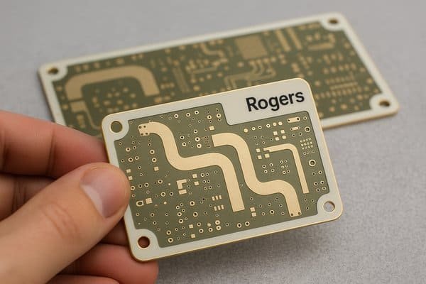
Rogers PCB boards are specialized printed circuit boards made with high-frequency laminate materials from Rogers Corporation. They provide superior, stable electrical performance, especially for RF and microwave applications, far exceeding standard FR-4 in critical parameters like dielectric constant consistency and low signal loss.
Understanding the nuances of PCB materials is crucial for any hardware engineer. When I first started designing RF circuits, I quickly learned that not all PCBs are created equal. The choice of material can be the difference between a successful product and a costly redesign. Rogers materials are a name that frequently comes up in high-performance circles, and for good reason. If you're pushing the boundaries of frequency and signal integrity, you'll want to know more about what they offer. Let's explore this topic further.
What are the different types of PCB boards?
Overwhelmed by PCB choices? Selecting the wrong one means project failure. Understanding different types helps ensure your design success from the start.
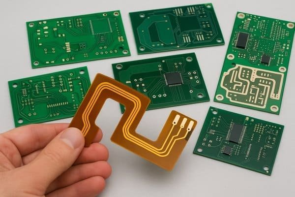
PCBs come in various forms: single-sided, double-sided, multilayer, rigid, flexible (flex), rigid-flex, and specialized high-frequency boards like those made with Rogers materials. Each type is tailored for specific applications and complexities.
When we talk about PCBs, it's not a one-size-fits-all situation. I've worked with a wide array of them in my career, and each has its place.
Common PCB Types
The most basic are single-sided PCBs, with components and conductive traces on only one side, typically found in very simple, low-cost electronics. Double-sided PCBs allow for more complex circuits by using both sides.
Then we have multilayer PCBs, which are standard for most modern electronics. These can range from 4 layers to 30 or more, sandwiching conductive layers between insulating layers. This density is essential for complex products like the Tuxedo Keypad I worked on at Honeywell.
Specialized PCB Types
Flexible PCBs (Flex PCBs), usually made from polyimide, allow circuits to bend or fold, crucial for wearables or devices with moving parts. Rigid-Flex PCBs combine the best of both, offering rigid sections for mounting components and flexible sections for interconnections.
And then there are high-frequency PCBs, which is where materials like Rogers shine. These are designed for applications where signal integrity at high speeds (GHz range) is critical, such as in communication systems or advanced sensor modules. For these, standard FR-4 often doesn't cut it. We also have metal-core PCBs (MCPCBs), often aluminum-backed, designed for superior heat dissipation in high-power applications like LED lighting.
Understanding these types helps you select the right foundation for your project.
What does FR4 stand for?
FR-4 is a common term, but do you know its precise meaning? Misunderstanding this fundamental material can lead to unexpected design issues, especially at higher frequencies.
FR-4 stands for "Flame Retardant, type 4." It's a NEMA (National Electrical Manufacturers Association) grade designation for a glass-reinforced epoxy laminate material, widely used for its good balance of cost, manufacturability, and electrical insulation.
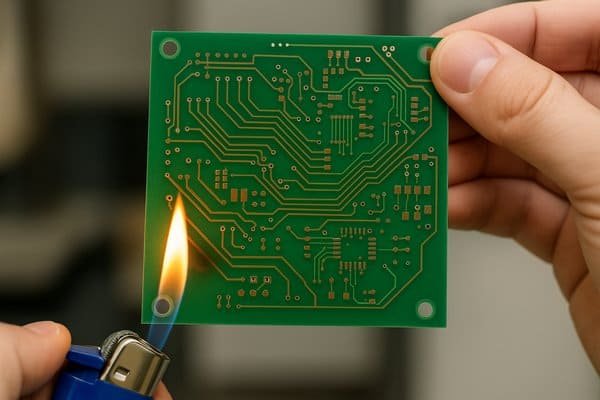
FR-4 is the workhorse of the PCB industry. The "FR" means it's flame retardant, a critical safety feature. The "4" indicates it's made from woven glass fabric impregnated with an epoxy resin binder. According to NEMA LI 1-1998 (R2011)1, this standard defines its properties.
For many applications, FR-4 is perfectly adequate. It offers good mechanical strength, excellent electrical insulation at lower frequencies, and is relatively inexpensive to manufacture. I've used it in countless projects, from industrial automation to security systems. However, its limitations become apparent as you move into higher frequency domains, typically above 1-3 GHz. At these frequencies, the dielectric constant2 (Dk) of FR-4 can vary significantly with frequency and temperature, and its dissipation factor3 (Df), or loss tangent, is relatively high. This means more signal loss and less predictable circuit behavior, which can be a major headache for RF engineers, who demand precision. While great for general-purpose use, for designs where consistent high-frequency performance is key, we often need to look beyond FR-4.
What is Rogers made of?
Curious about Rogers materials? Choosing them without understanding their composition is like navigating without a map. Knowing what makes them special is key to leveraging their benefits.
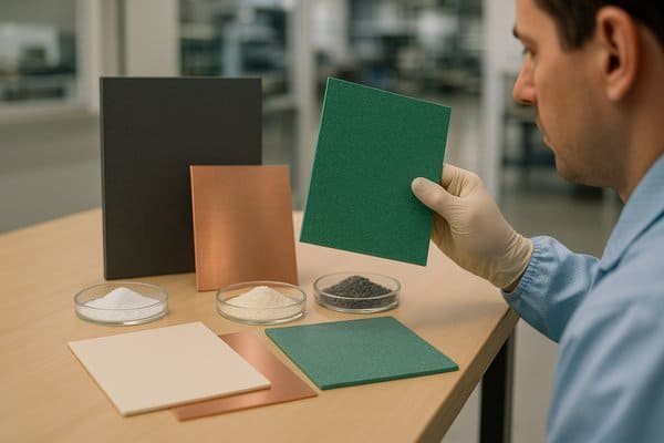
Rogers materials are specialized laminates, primarily composed of ceramic-filled Polytetrafluoroethylene (PTFE) or hydrocarbon-based thermoset plastics. These formulations provide exceptionally stable dielectric properties critical for high-frequency and high-speed performance.
Rogers Corporation produces a variety of high-performance materials, and they are not all the same. The "magic" in Rogers materials comes from their carefully engineered compositions. For instance, their popular RT/duroid® series4 (like RT/duroid 5880 or 6002) often uses PTFE (Teflon) reinforced with glass microfibers or filled with ceramics. PTFE is known for its very low electrical loss and stable dielectric constant. The addition of ceramic fillers helps to tailor the dielectric constant and improve mechanical stability.
Another well-known family is the RO4000® series5 (like RO4003C™ or RO4350B™). These are generally hydrocarbon ceramic thermoset laminates. They are easier to process than PTFE-based materials – more like FR-4 in terms of fabrication – while still offering excellent high-frequency performance. For example, Rogers RO4350B material, as per its datasheet, uses a hydrocarbon resin system with ceramic fillers and woven glass reinforcement. This combination results in low dielectric loss6, a tightly controlled dielectric constant, and low Z-axis thermal expansion, making it very reliable for multilayer constructions. This focus on material science is why Rogers can offer the predictability I mentioned earlier.
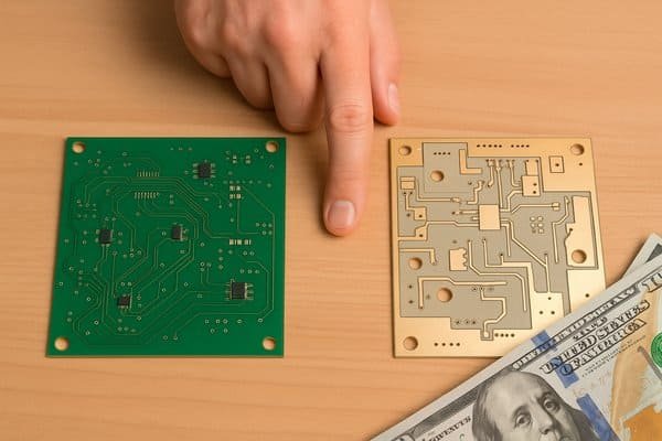
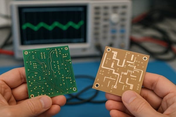
What is the difference between Rogers and FR4 PCB?
FR-4 or Rogers? The wrong choice can significantly impact your RF design's success or failure. Knowing the key differences is absolutely vital for informed decision-making.
The main differences between Rogers and FR-4 PCBs lie in their electrical performance at high frequencies, material cost, and sometimes fabrication processing. Rogers materials offer highly stable dielectric constant (Dk) and much lower dissipation factor (Df) compared to FR-4, but come at a premium price.
When I'm evaluating materials for a new project, especially one involving RF or high-speed digital signals, the comparison between FR-4 and a Rogers material is a frequent consideration. The insights I've gathered over the years, and which are critical to understand, revolve around electrical performance.
Here’s a breakdown:
| Feature | Standard FR-4 | Rogers Materials (e.g., RO4000, RT/duroid series) |
|---|---|---|
| Dielectric Constant (Dk) Stability | Poorer; varies significantly with frequency, temperature, and humidity. Typical Dk ~4.2-4.8. | Excellent; very stable Dk over wide frequency and temperature ranges. Specific, controlled Dk values (e.g., 2.2 to 10.2). |
| Dissipation Factor (Df) / Loss Tangent | Higher; typically 0.015-0.025 at 1 GHz. Leads to more signal loss. | Much lower; e.g., RO4350B Df is 0.0037 at 10 GHz. Results in significantly less signal attenuation. |
| Operating Frequency Range | Generally suitable for <1-3 GHz. Performance degrades rapidly above this. | Excellent for applications from 1 GHz up to 77 GHz and beyond, depending on the specific material. |
| Cost | Lower. | Significantly higher (5x to 20x+ material cost). |
| Thermal Conductivity | Lower; typically around 0.25-0.3 W/mK. | Varies; some Rogers materials (e.g., 92ML™ series) offer enhanced thermal conductivity (up to 1-2 W/mK or more). |
| Moisture Absorption | Higher. | Generally lower, leading to more stable electrical properties. |
| Processing | Standard, well-established processes. | May require specialized tooling, drilling parameters, and plasma treatment for PTFE-based materials. Hydrocarbon-based (like RO4000) are easier, similar to FR-4. |
The core value of Rogers, as I highlighted in my insights, is that predictable and highly consistent electrical performance7. For an engineer who handles everything from design to debugging, this predictability is gold. It means simulations are more likely to match real-world performance, reducing iterations and debugging time.
Under what circumstances should Rogers PCBs be chosen?
Using FR-4 for high-frequency designs often leads to failure. Performance suffers, and costs escalate. Rogers PCBs offer a reliable solution when signal integrity is paramount.
Rogers PCBs should be chosen for applications demanding stable electrical performance at high frequencies (typically >1-3 GHz), low signal loss, tight impedance control, and operation in challenging thermal or environmental conditions where FR-4's properties are inadequate.
Deciding to use a Rogers PCB isn't always straightforward because of the cost. However, in my experience, certain situations absolutely demand them.
| Application Scenario | Key Challenge / Requirement | Why Rogers PCBs are Chosen (Benefit) | Example Rogers Material Property / Advantage |
|---|---|---|---|
| High-Frequency RF & Microwave | Circuits operating >1-3 GHz (e.g., antennas, PAs, filters, 24/77 GHz radar). High signal loss and Dk instability with FR-4. | Essential for predictable performance; avoids impossible tuning. | Low Dissipation Factor (Df) (e.g., RO4350B Df ~0.0037 @ 10 GHz vs. FR-4 Df ~0.02 @ 1 GHz). Stable Dielectric Constant (Dk). |
| High-Speed Digital Circuits | Very high-speed signals (>10 Gbps SERDES), especially over long trace lengths. Risk of signal integrity issues (eye diagram closure). | Improves signal integrity. | Lower signal loss. Better and more consistent impedance control. (Alternatives like Megtron 6 also applicable). |
| Designs Requiring Extreme Dk Stability | Applications like sensitive GPS receivers, resonant cavities, scientific instruments. Dk needs to be constant over wide temperature ranges and batch-to-batch. | Provides exceptional Dk stability. | Materials like the Rogers RT/duroid® series are specifically designed for this. |
| Applications with Stringent Loss Budgets | Systems where every fraction of a decibel (dB) of signal loss matters (e.g., satellite communications, very sensitive receivers). | Minimizes signal attenuation. | Significantly lower Dissipation Factor (Df) compared to FR-4, leading to less signal power lost in the dielectric. |
What is better than FR4?
Seeking alternatives to FR-4? Sticking with it for demanding high-speed or high-frequency designs can severely limit your circuit's performance. Explore superior options for specific needs.
"Better" is application-dependent. For high-frequency, low-loss requirements, materials like Rogers, Taconic, or Arlon are superior to FR-4. For high thermal dissipation needs, metal-core PCBs (MCPCBs) or materials with enhanced thermal conductivity are better.
While FR-4 is a fantastic general-purpose material, there are many scenarios where "better" options exist. The key is to define what "better" means for your specific application.
If your primary concern is high-frequency performance8 (e.g., >3 GHz) and low signal loss, then FR-4 is often not the best choice. Here, materials like:
- Rogers Corporation materials (e.g., RO4000 series, RT/duroid series): As discussed, these offer excellent Dk stability and low Df. For instance, RO4350B (Dk ~3.48, Df ~0.0037 @ 10GHz) is a popular choice.
- Taconic Advanced Dielectric Division materials: They offer a range of PTFE and ceramic-filled laminates, similar to Rogers, for RF and microwave applications. For example, their TLY series has Dk values around 2.17-2.33.
- Arlon Electronic Materials: Another supplier of high-performance laminates, including polyimide and low-loss thermoset materials.
- Panasonic Megtron 6/7/8: These are advanced hydrocarbon-based materials known for very low loss and suitability for high-speed digital and RF applications. Megtron 6, for example, has a Dk around 3.3-3.7 and Df around 0.002-0.004 at high frequencies.
If thermal management9 is your main challenge, then materials better than standard FR-4 include: - Metal Core PCBs (MCPCBs): These use a metal base (usually aluminum) for excellent heat dissipation.
- Rogers 92ML™ Series or TC Series™: These are thermally conductive laminates designed to spread heat effectively.
If extreme temperatures or flexibility are needed, then polyimide or specialized high-temperature FR-4 variants might be "better." The crucial thing is to match the material properties to your design's critical requirements.
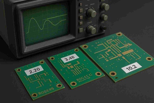
What is the dielectric constant of Rogers material?
Dk matters immensely for RF. Using incorrect or unstable Dk values in your simulations will absolutely cause real-world performance failures. Getting precise Rogers Dk information is critical.
Rogers materials offer a wide range of precise and highly stable dielectric constant (Dk) values, typically from around 2.2 up to 10.2 or higher. For example, RT/duroid 5880 has a Dk of 2.20, RO4350B is 3.48, and RT/duroid 6010LM is 10.2 (all values +/- tolerances, measured at specific frequencies, typically 10 GHz).
The dielectric constant (Dk), or relative permittivity (εr), is a fundamental property of an insulating material that affects how an electric field (and thus an electromagnetic wave) propagates through it. In PCB design, Dk is critical for:
- Controlled Impedance10: Transmission line impedance (e.g., 50 ohms) depends directly on the Dk of the substrate, trace width, and dielectric thickness.
- Signal Propagation Speed: Signals travel slower in materials with higher Dk.
- Filter and Antenna Design: The physical dimensions of resonant structures are inversely related to the square root of Dk.
What sets Rogers materials apart isn't just the range of Dk values they offer, but the stability and tolerance11 of these values. For instance, Rogers Corporation's datasheets provide detailed Dk specifications:
| Rogers Material | Process Dk (at 10 GHz, z-axis) | Design Dk (for simulation) | Typical Tolerance |
|---|---|---|---|
| RT/duroid® 5880 | 2.20 | 2.20 | +/- 0.02 |
| RO4003C™ | 3.38 | 3.55 | +/- 0.05 |
| RO4350B™ | 3.48 | 3.66 | +/- 0.05 |
| RO3003™ | 3.00 | 3.00 | +/- 0.04 |
| RT/duroid® 6010LM | 10.2 | 10.2 - 10.7 (application dependent) | +/- 0.25 - 0.5 |
Source: Rogers Corporation datasheets for respective materials.
This stability over frequency, temperature, and batch-to-batch variation is precisely what I emphasized in my insights. For an engineer, this means the Dk value used in simulations (often the "Design Dk" recommended by Rogers, which accounts for typical manufacturing effects) will closely match the actual Dk of the fabricated PCB. This predictability is invaluable for first-pass success in high-frequency designs. FR-4, in contrast, can have Dk variations of ±10% or more, which is unacceptable for precise RF work.
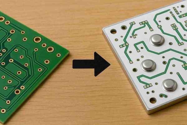
What is the difference between prepreg and core?
Prepreg? Core? Confusing these fundamental PCB construction terms can easily lead to stack-up errors and manufacturing problems. Understanding their distinct roles is essential for multilayer board success.
Core is a rigid laminate, typically a dielectric material (like FR-4 or Rogers) fully cured and clad with copper foil on one or both sides. Prepreg (pre-impregnated) is a B-stage (partially cured) dielectric material, usually a fiberglass cloth infused with resin, used to bond core layers together or to bond copper foil to a core in multilayer PCBs.
When I design multilayer PCBs, whether for complex digital systems or RF modules, understanding the roles of core and prepreg is fundamental to defining the stack-up.
- Core Material:
- This is a piece of dielectric substrate that is fully cured (C-stage) and typically has copper foil laminated to one or both sides by the material manufacturer. For example, you can buy an "RO4350B core" of a specific thickness (e.g., 0.020 inches or 0.508 mm) with 1 oz copper on both sides.
- Cores form the foundational layers of a multilayer PCB. They provide mechanical rigidity and stable dielectric properties. The thickness of the core dielectric is well-controlled.
- Prepreg Material:
- Prepreg consists of woven glass fabric (or other reinforcement) that has been impregnated with a resin system (like epoxy for FR-4, or specialized resins for high-frequency materials). The resin is only partially cured to a "B-stage." This makes it tacky and flowable when heated.
- During PCB lamination, layers of core and prepreg are stacked together with copper foil for outer layers. Under heat and pressure in a lamination press, the prepreg resin flows, fills gaps, and then fully cures, bonding the layers into a monolithic structure.
- Prepreg thickness after lamination is less precisely controlled than core thickness but is critical for impedance calculations. Manufacturers specify the "pressed thickness."
Rogers Corporation provides both core materials (e.g., RO4003C, RO4350B) and compatible bonding materials like RO4400 series prepregs (e.g., RO4450B) or 2929 Bondply. Using compatible materials ensures consistent electrical performance throughout the stack-up. As per IPC-410112 (Specification for Base Materials for Rigid and Multilayer Printed Boards), these materials have defined properties crucial for reliable PCB manufacturing.
How much does Rogers PCB material cost?
Rogers materials are known for high performance, but also higher cost. Can you justify it for your project? Not understanding the price difference can unfortunately wreck your budget.
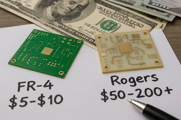
Rogers PCB material typically costs 5 to 20 times more per unit area than standard FR-4. For example, if a small 100mm x 100mm, 2-layer FR-4 prototype costs $5-$10 for the bare board, a similar Rogers PCB could range from $50 to $200+, depending on the specific Rogers material and quantity.
It's true, the initial reaction many engineers have to Rogers materials is "sticker shock." There's no denying they are significantly more expensive than FR-4. Providing exact dollar figures is tricky because costs depend on many factors:
- The specific Rogers material series (e.g., RT/duroid PTFE-based materials13 are generally more expensive than RO4000 hydrocarbon-based).
- Material thickness and copper weight.
- Panel utilization and waste.
- Order volume (prototypes vs. mass production).
- The PCB manufacturer's markup and processing capabilities.
However, to give a rough idea for material cost alone (not the finished PCB fabrication cost):
- Standard FR-4 laminate (e.g., 1.6mm, 1 oz copper) might cost in the range of $20 - $50 per square meter.
- Rogers RO4350B™ material, a popular choice, could be in the range of $200 - $600 per square meter.
- High-end PTFE-based Rogers materials like RT/duroid® 5880 could be even higher, perhaps $500 - $1500+ per square meter.
Beyond the raw material, fabrication costs for Rogers PCBs can also be higher, especially for PTFE-based materials. These may require specialized drilling techniques, plasma etching for plated through-hole preparation, and more careful handling.
So, why pay the premium? As I've stressed, it's for performance and predictability in demanding applications. If your product operates at GHz frequencies, requires low signal loss, or needs extremely stable impedance control, the higher cost of Rogers can be easily justified by:
- Reduced design iterations and faster time-to-market.
- Improved product performance and reliability.
- Avoiding field failures due to signal integrity issues14.
For engineers who value quality and reliability, this upfront investment often pays off by preventing costly downstream problems. The best approach is always to get quotes from PCB manufacturers specifying the exact Rogers material you need.
Conclusion
Rogers PCBs, with their specialized materials, provide unmatched high-frequency performance and electrical stability. While they cost more, they are indispensable for demanding RF and microwave applications where precision is key.
-
This standard outlines the properties of FR-4, providing essential guidelines for its use in various applications. ↩
-
Understanding the dielectric constant is crucial for RF engineers to ensure optimal circuit performance at high frequencies. ↩
-
Exploring the dissipation factor helps in assessing signal loss and circuit behavior, essential for high-frequency applications. ↩
-
Explore the RT/duroid® series to understand its unique properties and applications in high-performance materials. ↩
-
Discover the advantages of the RO4000® series and how it compares to other materials in high-frequency performance. ↩
-
Learn about the significance of low dielectric loss in enhancing the performance and reliability of electronic components. ↩
-
This concept is vital for reducing design iterations and ensuring reliability in RF applications. Discover more about its impact here. ↩
-
Explore this link to discover advanced materials that outperform FR-4 in high-frequency applications, ensuring optimal signal integrity. ↩
-
Learn about innovative materials that excel in thermal management, crucial for maintaining performance in high-power applications. ↩
-
Exploring controlled impedance will help you grasp its importance in maintaining signal integrity and performance in PCBs. ↩
-
Learn about stability and tolerance to ensure reliable performance in PCB manufacturing and design, especially for RF applications. ↩
-
Learn about IPC-4101 standards to ensure your PCB materials meet industry requirements for reliability and performance. ↩
-
Learn about PTFE-based materials and their unique properties that make them suitable for high-performance PCBs. ↩
-
Discover how signal integrity issues can impact your PCB designs and why addressing them is crucial for reliability. ↩


