 Skip to content
Are you struggling to select the right PCB material for your high-frequency design? The wrong choice can cripple performance, leading to signal loss and instability, ultimately jeopardizing your entire project timeline. Understanding the core electrical properties is crucial for success.
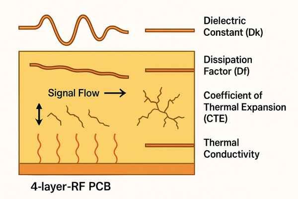
The key electrical properties of RF PCB materials are the dielectric constant (\(D_{k}\)), dissipation factor (\(D_{f}\)), coefficient of thermal expansion (CTE), and thermal conductivity. These properties directly impact signal integrity, impedance control, power loss, and the physical reliability of the circuit, especially at high frequencies.
Choosing the right material for a Radio Frequency (RF) Printed Circuit Board (PCB) is one of the most critical decisions an engineer makes. It's not just about getting the circuit to work; it's about ensuring it works reliably across different temperatures and frequencies. In my nearly 20 years as a hardware engineer, I've seen how a seemingly small mismatch in material properties can derail a project, turning a promising prototype into a source of endless debugging. Let's dive into the properties that really matter, so you can avoid these pitfalls and build robust, high-performance RF systems.
What Is the Dielectric Constant (Dk) and Why Is It Important for RF Circuits?
Feeling lost in a sea of material datasheets? The dielectric constant, or \(D_{k}\), is a fundamental property that dictates how an electric field, and thus your RF signal, behaves within the PCB material, directly impacting your circuit's performance.
The dielectric constant (\(D_{k}\)), or relative permittivity (\(\epsilon_{r}\)), measures a material's ability to store electrical energy. For RF circuits, a stable and well-defined \(D_{k}\) is critical for maintaining controlled impedance, ensuring predictable signal propagation, and determining the physical size of transmission lines.
The dielectric constant is more than just a number on a datasheet; it's a cornerstone of RF design. It defines the relationship between the physical geometry of your traces and their electrical behavior. Any deviation from the expected \(D_{k}\) can cause a cascade of problems that are difficult to trace back to the source. In my experience with high-frequency designs like Wi-Fi modules, getting the \(D_{k}\) right is the first step toward a functional circuit. A stable \(D_{k}\) ensures that your design simulations match real-world performance, saving you from costly and time-consuming board respins.
How Dk Affects Controlled Impedance
Controlled impedance is essential for preventing signal reflections and maximizing power transfer in RF systems. The impedance of a common transmission line structure, like a microstrip, is heavily dependent on the substrate's \(D_{k}\). Even small variations can shift the impedance away from the standard 50 ohms. For instance, the impedance (\(Z_{0}\)) of a surface microstrip is a function of the trace width (\(W\)), substrate height (\(H\)), and the effective dielectric constant (\(\epsilon_{eff}\)), which is derived from \(D_{k}\). A slight increase in \(D_{k}\) will decrease the trace impedance if the physical dimensions are kept constant. For sensitive matching networks, a deviation of just 2-3 ohms can detune the circuit and degrade performance significantly. This is why you can't simply swap a material like Rogers RO4350B1 (\(D_{k} = 3.48\)) with standard FR-4 (\(D_{k} \approx 4.5\)) without completely recalculating and resizing your RF trace geometries.
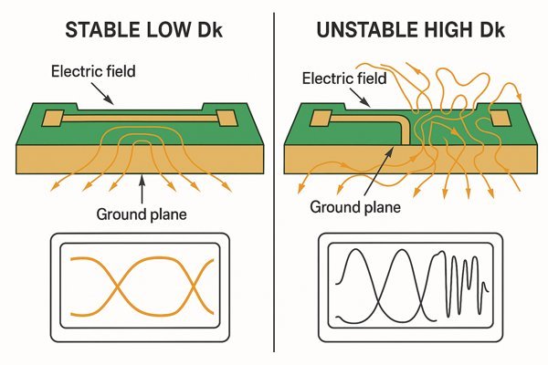
Dk Stability: The Real Key to Performance
While a low \(D_{k}\) is often desirable for faster signal propagation, a stable \(D_{k}\) across frequency and temperature is far more critical for broadband and high-performance applications. Standard FR-4 is notoriously unstable; its \(D_{k}\) can drop by as much as 10% as the frequency rises from 1 MHz to 10 GHz. This makes it impossible to maintain consistent impedance over a wide frequency band. High-frequency laminates are engineered for stability. According to their datasheets, materials from Rogers' RO4000 series exhibit minimal change in \(D_{k}\) across their operating frequency range.
| Material | \(D_{k}\) @ 1 GHz | \(D_{k}\) @ 10 GHz | Stability |
|---|---|---|---|
| Standard FR-4 | \(\approx 4.7\) | \(\approx 4.3\) | Poor |
| Isola IS410 | \(\approx 3.95\) | \(\approx 3.87\) | Fair |
| Rogers RO4350B™ | 3.48 | 3.48 | Excellent |
Data sourced from Isola and Rogers Corporation datasheets.
This stability ensures your filters, couplers, and matching networks perform as designed, not just at one frequency, but across the entire operational spectrum.
What Is the Dissipation Factor (Df), or Loss Tangent, and How Does It Affect Signal Loss?
Are your high-frequency signals losing too much power? This loss, often called insertion loss, can be a major headache, and the dissipation factor of your PCB material is a primary culprit, directly turning your signal into wasted heat.
The dissipation factor (\(D_{f}\)), also known as the loss tangent (\(\tan\delta\)), quantifies how much of a signal's electromagnetic energy is absorbed and lost as heat within the PCB's dielectric material. A lower \(D_{f}\) is essential for minimizing signal attenuation, especially at microwave frequencies.
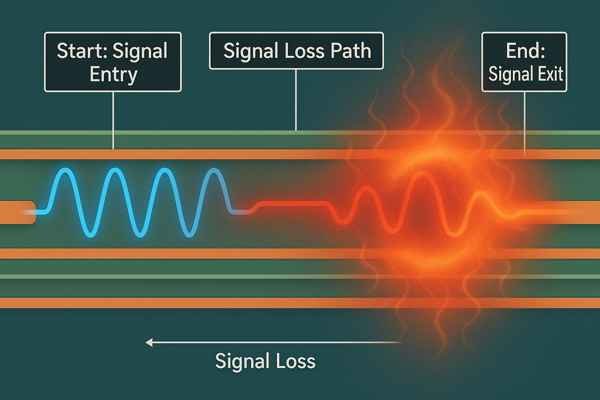
Think of the dissipation factor as a measure of the material's electrical inefficiency. As a signal travels through the substrate, some of its energy is consumed by the dielectric. This is known as dielectric loss, and it becomes progressively worse as the frequency increases. I once worked on a 5 GHz Wi-Fi module where the prototype, built on standard FR-4 to save costs, had abysmal range. The high \(D_{f}\) of the FR-4 was literally eating our signal power before it even reached the antenna. Switching to a low-loss laminate made the difference between a failed product and a successful one.
Breaking Down Total Signal Loss
The total insertion loss in a PCB trace comes from three main sources: conductor loss (due to copper's resistance and skin effect), radiation loss (energy escaping into the environment), and dielectric loss. The dielectric loss is directly proportional to the dissipation factor2. At lower frequencies (\(<1 \text{ GHz}\)), conductor loss is often the dominant factor. However, as frequency increases into the microwave range (\(>3 \text{ GHz}\)), dielectric loss driven by \(D_{f}\) quickly becomes the largest contributor to total signal attenuation. This is why for applications like 24 GHz automotive radar or 28 GHz 5G infrastructure, choosing a material with an extremely low \(D_{f}\) is non-negotiable.
The Frequency Dependence of Df
Dielectric loss, in dB per unit length, increases nearly linearly with frequency and the dissipation factor. A simplified rule of thumb is that every time you double the frequency, you double the dielectric loss. Therefore, a material with a seemingly acceptable \(D_{f}\) at 1 GHz can become completely unusable at 10 GHz. For demanding applications, engineers must select materials with the lowest possible \(D_{f}\). According to material manufacturer Rogers Corporation, their RO4350B material has a \(D_{f}\) of \(0.0037\) at 10 GHz, while their RO30033 material offers an even lower \(D_{f}\) of \(0.0013\), making it suitable for millimeter-wave frequencies.
| Material | Dissipation Factor (\(D_{f}\)) @ 10 GHz | Performance |
|---|---|---|
| Standard FR-4 | \(\approx 0.020\) | High Loss (Unsuitable for \(>2 \text{ GHz}\)) |
| Panasonic Megtron 6 | \(\approx 0.004\) | Very Low Loss (Good for \(>10 \text{ GHz}\)) |
| Rogers RO3003™ | 0.0013 | Extremely Low Loss (mmWave) |
Data sourced from manufacturer datasheets.
Choosing a material with a low \(D_{f}\) is a direct investment in your signal's power budget.
What Is the Coefficient of Thermal Expansion (CTE), and Why Does It Matter in Multilayer PCBs?
Ever had a PCB fail during thermal cycling, with no obvious electrical fault? The hidden culprit might be a mismatch in the Coefficient of Thermal Expansion (CTE), causing immense physical stress on your board's structures until something breaks.
The Coefficient of Thermal Expansion (CTE) measures how much a material expands or contracts for each degree Celsius change in temperature. In multilayer PCBs, a low and consistent CTE is vital to prevent delamination, via cracking, and component failure during temperature fluctuations.
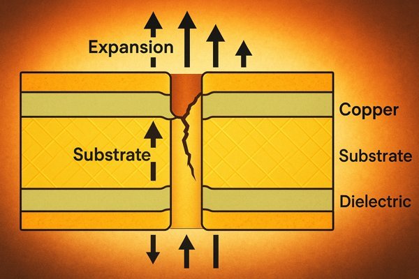
A PCB is a composite of copper, fiberglass, and resin, each expanding at a different rate. This mismatch is the root of many reliability problems, especially in products that operate in harsh environments. I've seen this firsthand in automotive and aerospace projects where electronics must survive temperature swings from \(-40^{\circ}\text{C}\) to \(+125^{\circ}\text{C}\). A high Z-axis CTE can literally rip a plated through-hole apart after enough cycles, leading to intermittent failures that are a nightmare to diagnose. This is why a deep understanding of CTE is critical for designing products that are built to last.
The Critical Role of Glass Transition Temperature (\(T_{g}\))
The glass transition temperature4, or \(T_{g}\), is the temperature at which the PCB's resin matrix changes from a rigid, glassy state to a more pliable, rubbery one. Below \(T_{g}\), the Z-axis CTE of a material like FR-4 is already high, typically around \(50-70 \text{ ppm/}^{\circ}\text{C}\). However, once the temperature exceeds \(T_{g}\), the expansion rate skyrockets, often to over \(250 \text{ ppm/}^{\circ}\text{C}\). In contrast, the CTE of copper is only about \(17 \text{ ppm/}^{\circ}\text{C}\). This massive difference in expansion puts enormous tensile stress on the copper barrel of a plated via. According to the IPC-A-600 standard, this stress is a leading cause of via fatigue and failure. For high-reliability applications, it is crucial to select a material with a \(T_{g}\) well above the maximum operating temperature of the product.
Mitigating Stress on Vias and Solder Joints
The primary concern with high CTE is the reliability of plated through-holes (PTHs) and vias. The repeated expansion and contraction of the Z-axis during thermal cycling causes a fatigue mechanism known as "barrel cracking" or "pad lifting." To ensure long-term reliability, engineers must select materials where the Z-axis CTE is more closely matched to that of copper. High-performance RF materials are specifically engineered for this. For example, materials in the Rogers RO4000 series5 have a Z-axis CTE around \(30-50 \text{ ppm/}^{\circ}\text{C}\), which is much closer to copper's CTE and remains stable well beyond typical operating temperatures. This minimizes the strain on the vias, dramatically improving the product's lifespan, particularly in multilayer boards with blind and buried vias.
| Property | Copper | Standard FR-4 (\(T_{g} \approx 135^{\circ}\text{C}\)) | Rogers RO4350B™ (\(T_{g} > 280^{\circ}\text{C}\)) |
|---|---|---|---|
| CTE (Z-axis, below \(T_{g}\)) | \(\approx 17 \text{ ppm/}^{\circ}\text{C}\) | \(\approx 60 \text{ ppm/}^{\circ}\text{C}\) | \(32 \text{ ppm/}^{\circ}\text{C}\) |
| CTE (Z-axis, above \(T_{g}\)) | N/A | \(>250 \text{ ppm/}^{\circ}\text{C}\) | N/A (Stable) |
What Is the Thermal Conductivity of PCB Materials?
Is your power amplifier overheating and threatening to shut down or fail permanently? The ability of your PCB to dissipate that damaging heat is directly linked to the thermal conductivity of its base material.
Thermal conductivity measures a material's ability to conduct heat. In PCBs, higher thermal conductivity helps dissipate heat generated by active components, preventing overheating, improving performance, and increasing the long-term reliability of the device.
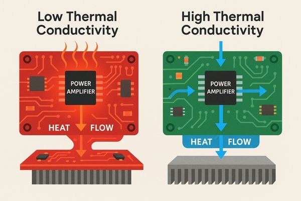
Many RF components, especially power amplifiers (PAs), generate a significant amount of heat. This heat must be efficiently removed from the component's semiconductor junction to prevent it from exceeding its maximum safe operating temperature. While large copper ground planes and arrays of thermal vias are the primary tools for heat management, the substrate material itself plays a crucial supporting role. A material with poor thermal conductivity acts like an insulator, trapping heat directly under the component and creating a critical hot spot.
Comparing Thermal Conductivity Across Materials
The difference in thermal conductivity6 between materials is substantial. Standard FR-4 is fundamentally a thermal insulator, with a typical value of only \(0.25 \text{ W/m·K}\). In contrast, copper, which we use for traces and planes, is an excellent thermal conductor at around \(386 \text{ W/m·K}\). This disparity highlights why our design strategies focus on moving heat into copper as quickly as possible. Specialized RF materials often incorporate ceramic fillers to improve thermal performance. For instance, Rogers RO4350B™ has a thermal conductivity of \(0.69 \text{ W/m·K}\), more than twice that of FR-4. For extreme power applications, engineers use Insulated Metal Substrates (IMS), which feature a metal baseplate (usually aluminum) and can achieve thermal conductivity values of \(2.0 \text{ W/m·K}\) or higher.
| Material Type | Example | Thermal Conductivity (\(\text{W/m·K}\)) |
|---|---|---|
| Standard Epoxy | FR-4 | \(\approx 0.25\) |
| Ceramic-filled Hydrocarbon | Rogers RO4350B™ | 0.69 |
| IMS (Aluminum Base) | Bergquist T-Clad | \(>2.0\) |
| Ceramic Substrate | Aluminum Nitride (AlN) | \(\approx 170\) |
Data compiled from manufacturer datasheets and industry publications.
Design Strategies for Effective Heat Spreading
Even with a better material, good thermal design is crucial. The goal is to create a low-resistance thermal path from the heat source to the ambient environment. This involves several techniques:
- Thermal Vias: Placing an array of vias directly under the thermal pad of a hot component. These vias act as conduits, efficiently wicking heat from the top layer down to internal or bottom-side ground planes.
- Large Copper Planes: Using extensive, solid copper planes as heatsinks. These planes spread the heat laterally, reducing the temperature concentration.
- Component Placement: Avoid placing multiple high-power components close together to prevent the formation of a large, combined hot spot.
By selecting a material with higher thermal conductivity and implementing sound thermal design practices, you can ensure your components run cooler, perform better, and last longer.
Conclusion
Selecting the right RF material involves a critical trade-off between electrical performance, thermal reliability, and cost. By understanding \(D_{k}\), \(D_{f}\), CTE, and thermal conductivity, you can make an informed engineering decision.
-
Explore the advantages of Rogers RO4350B for stable performance in RF applications, ensuring optimal signal integrity. ↩
-
Understanding the dissipation factor is crucial for selecting materials that minimize signal loss in high-frequency applications. ↩
-
Discover the advantages of Rogers RO3003, a top choice for low-loss applications in millimeter-wave frequencies. ↩
-
Understanding glass transition temperature is crucial for selecting materials in high-reliability applications, ensuring durability and performance. ↩
-
Discover how Rogers RO4000 series materials can enhance PCB performance and reliability, especially in high-frequency applications. ↩
-
Understanding thermal conductivity is essential for selecting materials in engineering applications, ensuring optimal performance and efficiency. ↩


