 Skip to content
Struggling to choose the right PCB material for your RF design? The wrong choice can lead to signal loss and poor performance, jeopardizing your entire project. You need a material that guarantees signal integrity at your target frequency without breaking the budget.
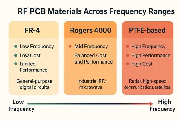
The most common RF PCB materials include standard FR-4 (for lower frequencies), hydrocarbon-based laminates like the Rogers 4000 series (a popular mid-range choice), and PTFE-based laminates (for high-performance, high-frequency applications). The best choice depends on frequency, performance requirements, and cost.
Choosing a PCB substrate is one of the most critical decisions in RF circuit design. It's a balancing act between electrical performance, mechanical properties, manufacturability, and of course, cost. In my nearly 20 years as a hardware engineer, I've seen projects succeed or fail based on this single choice. Let's break down the options to help you make an informed decision for your next RF project.
How Do FR-4 and High-Frequency Laminates Compare for RF Applications?
You're designing a new product and need to keep costs down. You see FR-4 is inexpensive and readily available, but you're worried it won't handle your RF signals properly. Will it work, or are you forced to use a more expensive high-frequency laminate?
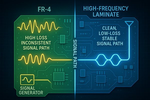
FR-4 can be used for RF applications up to \(1-2 \text{ GHz}\), but it suffers from high and unstable electrical losses. High-frequency laminates, like those from Rogers or Taconic, offer significantly lower and more stable dielectric constants (\(D_{k}\)) and dissipation factors (\(D_{f}\)) across frequency, ensuring reliable performance.
The primary trade-off between FR-4 and specialized high-frequency laminates comes down to performance versus cost. While standard FR-4 is the workhorse of the PCB industry, its properties become a major liability as frequencies climb. Let's dive deeper.
Dielectric Loss Tangent's Impact on Performance
The core issue with FR-4 is its high and unpredictable dielectric loss, quantified by the Dissipation Factor1 (\(D_{f}\)). This loss is cumulative and gets dramatically worse as frequency and signal path length increase. To put it in practical terms, a long trace on FR-4 can act like an attenuator, killing your signal before it gets to its destination. The table below illustrates the escalating problem.
| Frequency | Approx. Insertion Loss on FR-4 (\(\text{dB/inch}\)) | Approx. Insertion Loss on RO4350B (\(\text{dB/inch}\)) |
|---|---|---|
| \(1 \text{ GHz}\) | \(\approx 0.10\) | \(\approx 0.04\) |
| \(5 \text{ GHz}\) | \(\approx 0.35\) | \(\approx 0.10\) |
| \(10 \text{ GHz}\) | \(\approx 0.60\) | \(\approx 0.16\) |
As you can see, the loss on FR-4 at \(10 \text{ GHz}\) is nearly four times higher than on RO4350B. For a 4-inch trace, that's the difference between losing \(0.64 \text{ dB}\) of your signal versus losing a devastating \(2.4 \text{ dB}\).
The Challenge of Impedance Consistency
Precise \(50 \, \Omega\) impedance is crucial. FR-4's Dielectric Constant (\(D_{k}\)) is not only inconsistent across the material but also changes with frequency. This makes achieving a stable \(50 \, \Omega\) trace a guessing game. High-frequency laminates provide a very stable \(D_{k}\) across frequency and are manufactured to tight tolerances, ensuring your simulated impedance matches the final product.
A Deeper Material Property Comparison
Let's break down the key parameters in a more detailed table. This goes beyond just the main electrical specs to show the hidden factors that affect performance and reliability.
| Property | Standard FR-4 | High-Frequency Laminate (RO4350B) | Impact on RF Design |
|---|---|---|---|
| \(D_{k}\) Variation with Freq. | High (e.g., \(4.7\) @ \(1\text{MHz}\), \(\approx 4.3\) @ \(10\text{GHz}\)) | Very Low | Unpredictable impedance, phase velocity shifts. |
| \(D_{f}\) @ \(10 \text{ GHz}\) | \(\approx 0.020\) | \(0.0037\) | FR-4 has \(>5\text{x}\) more signal loss. |
| Moisture Absorption | \(0.10\% - 0.25\%\) | \(0.06\%\) | FR-4's performance degrades in humid environments. |
| Thermal Conductivity (\(\text{W/m-K}\)) | \(\approx 0.25\) | \(\approx 0.69\) | Laminate is \(\approx 3\text{x}\) better at dissipating heat. |
What Are The Differences Between Rogers 4350B and Rogers 4003C?
You're considering a Rogers 4000 series material for your design. You see both RO4350B and RO4003C mentioned frequently, and their specs look similar. How do you choose between them when the datasheets seem almost identical at first glance?
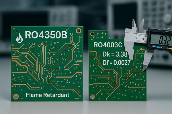
The main difference is that RO4350B is flame retardant (UL 94V-0 rated), while RO4003C is not. Electrically, they are very similar, but RO4003C has a slightly lower dielectric constant (\(3.38\) vs. \(3.48\)) and a lower dissipation factor (\(0.0027\) vs. \(0.0037\)), making it marginally better for loss-sensitive applications.
Choosing between these two popular materials often comes down to more than just the flammability rating. In my experience leading hardware development, the subtle differences in their properties can have a real impact on manufacturability and long-term reliability.
Electrical Performance in the Real World
That small difference in dissipation factor (\(D_{f}\)) between RO4003C (\(0.0027\)) and RO4350B (\(0.0037\)) might seem trivial, but in a cascaded system with multiple filters and amplifiers, those losses add up. For a sensitive receiver's Low Noise Amplifier (LNA) input path, choosing RO4003C could improve the overall noise figure by a fraction of a dB—a critical margin in high-performance systems.
Thermomechanical Stability and Via Reliability
A crucial but often overlooked spec is the Z-axis Coefficient of Thermal Expansion (\(\text{CTE}\)), which measures vertical expansion with heat. A large mismatch between the laminate and the copper plating in vias causes stress during temperature changes.
| Material | Z-Axis \(\text{CTE}\) (\(\text{ppm/}^{\circ}\text{C}\)) | Mismatch vs. Copper | Reliability Implication |
|---|---|---|---|
| Copper | \(\approx 17\) | - | Baseline |
| RO4350B | \(32\) | Low | Excellent long-term via reliability. |
| RO4003C | \(46\) | Moderate | Good reliability, but less robust than RO4350B under extreme thermal cycling. |
The lower \(\text{CTE}\) of RO4350B makes it a much more robust choice for products that will experience significant temperature swings, like automotive or aerospace electronics, as it minimizes the risk of via barrel cracking and failure over the product's lifetime.
Design Dk vs. Process Dk
Rogers datasheets list two \(D_{k}\) values. The "Process \(D_{k}\)" is for fabricator QC tests, while the "Design \(D_{k}\)" is a slightly higher value for circuit simulation software (like Keysight ADS or Ansys HFSS). Using the "Design \(D_{k}\)" is essential for getting your circuit geometry right the first time and ensuring your board performs as simulated.
When Is It Appropriate to Use PTFE-Based PCB Materials?
Your design operates at very high frequencies, perhaps in the millimeter-wave spectrum. Materials like Rogers 4000 series are good, but you need the absolute best performance available. When does it become necessary to step up to PTFE-based materials?
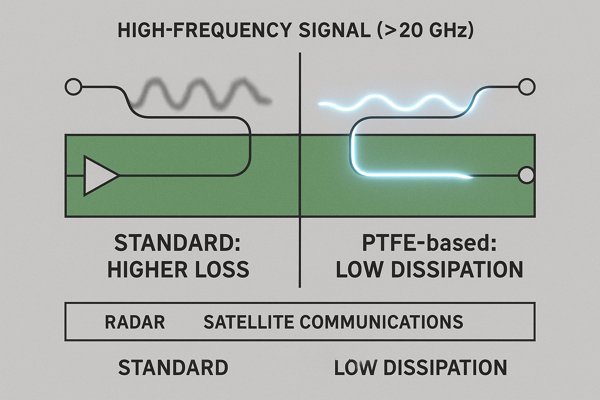
PTFE-based materials are appropriate for high-frequency applications (typically \(> 20 \text{ GHz}\)) and circuits where extremely low signal loss is critical. Their very low dissipation factor makes them ideal for millimeter-wave radar, satellite communications, and high-performance power amplifiers.
Polytetrafluoroethylene (PTFE) is the king of high-frequency performance. But stepping up to PTFE is a significant decision that involves major trade-offs in fabrication and cost. I only specify these materials when the application's physics absolutely demands them.
The Millimeter-Wave Frontier
As frequencies enter the millimeter-wave (mmWave) bands2, the physics of signal loss makes high-performance materials mandatory.
| Application | Frequency Band | Why PTFE3 is Needed |
|---|---|---|
| Automotive Radar | \(77 - 81 \text{ GHz}\) | Extremely low loss is required to achieve necessary sensor range and resolution. |
| 5G/6G Infrastructure | \(28 \text{ GHz}\), \(39 \text{ GHz+}\) | Minimizes signal attenuation in antenna arrays and feed networks. |
| Satellite Communications | Ka-Band (\(26.5-40 \text{ GHz}\)) | Ensures signal integrity for both uplink and downlink paths. |
| High-Speed Datacom | \(112 \text{ Gbps PAM4}\) | Preserves signal shape and eye-opening over long backplane traces. |
Fabrication Challenges in Detail
The reason PTFE is so expensive is not just the material itself, but the specialized fabrication it requires. It is fundamentally different from processing FR-4.
| Fabrication Step | PTFE Challenge | Standard Process (FR-4 / Rogers 4000) |
|---|---|---|
| Drilling | Soft material smears; requires special bits and de-smear cycles (e.g., plasma). | Hard material allows for clean drilling with standard bits. |
| Plating Prep | Chemically inert surface requires hazardous sodium etch to ensure via wall adhesion. | Standard chemical clean is sufficient for good plating adhesion. |
| Lamination | High \(\text{CTE}\) and softness lead to dimensional instability and registration issues. | Low \(\text{CTE}\) and rigidity ensure stable and accurate layer-to-layer alignment. |
Hybrid Stack-up Strategies
To balance cost and performance, a very common technique is to use a hybrid stack-up. For example, the top layers carrying critical RF signals might be PTFE, while the inner and bottom layers for DC power and control are FR-4. This gives you performance where needed without the expense of a pure PTFE build.
What Are The Best Low-Loss RF PCB Materials Available?
You need the best possible performance for a demanding application. You're looking for materials that go beyond the standard choices to offer the lowest possible signal loss. What are the top-tier, low-loss RF PCB materials on the market today?
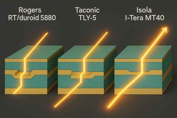
The best low-loss materials are typically PTFE-based laminates, either filled with ceramic or reinforced with woven glass. Materials like Rogers RT/duroid 5880 (\(D_{f} \approx 0.0009\)), Taconic TLY-5 (\(D_{f} \approx 0.0009\)), and Isola I-Tera MT40 (\(D_{f} \approx 0.0031\)) are industry leaders for high-performance RF applications.
When chasing every last fraction of a decibel, you must look beyond a single datasheet number and understand the complete picture of what contributes to signal loss.
Decoding Total Insertion Loss
Total insertion loss is a sum of multiple factors. At mmWave frequencies, the conductor loss can become as significant as the dielectric loss.
| Loss Mechanism | Primary Cause | Mitigation Strategy |
|---|---|---|
| Dielectric Loss | Signal energy absorbed by the laminate. | Choose a material with a very low Dissipation Factor (\(D_{f}\)). |
| Conductor Loss | Skin effect and resistance of the copper trace. | Use wider traces where possible; select laminates with very smooth copper foil. |
| Radiation Loss | Signal energy escaping into space (acting as an antenna). | Ensure proper trace geometry and a solid, continuous ground plane. |
The roughness of the copper foil is critical. A rougher surface increases the effective path length for the high-frequency current, increasing loss. Using materials with very smooth rolled-annealed (RA) copper instead of standard electrodeposited (ED) copper can make a measurable difference.
Top-Tier Low-Loss Materials
Here is a summary of some of the best-in-class materials from leading manufacturers.
| Material | Manufacturer | Base | \(D_{k}\) (@ \(10 \text{ GHz}\)) | \(D_{f}\) (@ \(10 \text{ GHz}\)) |
|---|---|---|---|---|
| RT/duroid 5880 | Rogers | PTFE / glass microfiber | \(2.20\) | \(0.0009\) |
| TLY-5 | Taconic | PTFE / woven glass | \(2.20\) | \(0.0009\) |
| I-Tera MT40 (RF/MW) | Isola | Hydrocarbon/Ceramic | \(3.45\) | \(0.0031\) |
| RO3003 | Rogers | PTFE / ceramic | \(3.00\) | \(0.0010\) |
The IPC-60184 Standard for High-Reliability
For aerospace, defense, and medical applications, boards must often comply with IPC-6018. This standard dictates stringent requirements for materials and manufacturing processes to ensure maximum reliability under harsh conditions. Compliance with IPC-6018 is a mark of quality and robustness, signifying that the PCB can withstand the rigorous thermal and mechanical stress tests demanded by high-stakes applications.
Conclusion
Choosing the right RF PCB material is a critical engineering decision. It involves balancing performance needs like frequency and signal loss against practical constraints like manufacturability and cost for your project.
-
Understanding the Dissipation Factor is crucial for evaluating dielectric loss in materials, impacting signal integrity and performance. ↩
-
Exploring this resource will provide insights into the diverse applications and significance of mmWave technology in modern communications. ↩
-
Understanding the role of PTFE in high-frequency applications can enhance your knowledge of material science and its impact on technology. ↩
-
Exploring IPC-6018 will provide insights into high-reliability standards essential for aerospace and medical applications, ensuring quality and durability. ↩


