 Skip to content
Struggling with a product that mysteriously freezes in the field? A simple software bug can lock up your microcontroller, making your device unresponsive and frustrating customers. A watchdog timer is the essential hardware fail-safe that prevents this from happening.
For any commercial or industrial product where reliability is a key requirement, a watchdog timer (WDT) is mandatory. It is a hardware-based timer that acts as an independent system monitor, automatically resetting a frozen microcontroller to ensure recovery from transient software faults or certain hardware-induced lockups.
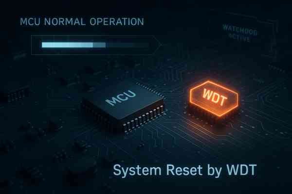
The principle of a watchdog is simple: your software must periodically "kick" the timer to let it know everything is running correctly. If the kick doesn't happen on time, the watchdog assumes the system has crashed and issues a reset. While the concept is straightforward, the engineering decisions involved—from choosing between internal and external supervisors to implementing them robustly—are what separate a reliable product from one that fails unpredictably.
What Is The Difference Between An Internal And An External Watchdog Timer?
You know a watchdog is necessary, but the MCU already has one built-in. Choosing between the internal WDT and adding an external one is a critical decision. Making the wrong choice could leave your system vulnerable to the exact failures you are trying to prevent.
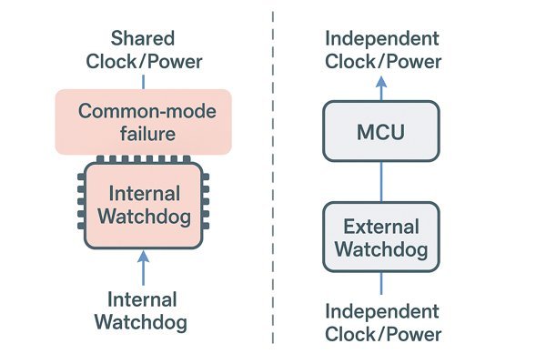
An internal watchdog is a peripheral built directly into the microcontroller, sharing its power, clock, and silicon. An external watchdog is a separate, dedicated IC. This physical and electrical independence is its key advantage, as it is not susceptible to common-mode failures that affect the entire MCU.
When I architect a system, this choice is one of the first I make, as it has implications for the Bill of Materials (BOM), PCB layout, and overall system reliability architecture.
Comparing Internal vs. External Watchdogs
This table summarizes the core trade-offs:
| Feature | Internal Watchdog Timer (IWDG) | External Watchdog Timer (WDT IC) |
|---|---|---|
| Integration | Integrated into the MCU silicon. Zero BOM cost. | Separate IC on the PCB. Adds $0.20 - $1.50 to BOM cost. |
| Clock Source | Uses one of the MCU's internal oscillators (e.g., LSI). Vulnerable to MCU-wide clock failure. | Has its own independent, factory-trimmed oscillator. Immune to MCU clock failure. |
| Fault Coverage | Cannot detect failures like MCU latch-up, severe power droop, or catastrophic clock failure. | Can detect MCU lock-up and provides precise voltage supervision (brown-out detection). |
| Software Vulnerability | Can be disabled by a software bug (e.g., a stray pointer writing to a control register). | Often has hardware-set or one-time-programmable (OTP) settings, making it immune to software tampering. |
| Typical Use Case | Low-cost consumer gadgets, non-critical applications. | High-reliability, safety-critical systems (medical, automotive, industrial, aerospace). |
Matching Watchdog Type to Application Risk
On the Honeywell Tuxedo Keypad project, which was a high-volume consumer product, the MCU's internal watchdog was deemed sufficient for the target market. However, for the Smiths Medical infusion pump I worked on, relying on an internal WDT was not an option. Medical device standards like IEC 60601-11 and the associated software standard IEC 623042 demand rigorous risk mitigation. An independent external supervisor was a non-negotiable component of our safety architecture to prevent a single fault from causing a catastrophic failure.
When Is An External Watchdog Timer IC Necessary Over An Internal One?
Your microcontroller datasheet proudly lists an "Independent Watchdog" feature. This sounds robust, but relying on it can create a false sense of security. Certain failure modes can knock out your MCU and its internal watchdog simultaneously, leaving your system bricked.
An external watchdog IC is necessary for any high-reliability or safety-critical system. Use one when the application cannot tolerate a lock-up, such as in medical devices, automotive control units (ASIL-rated), or industrial automation (SIL-rated), where a failure could have severe consequences.
An external watchdog provides true physical independence. Here are specific scenarios where it is mandatory.
Why External WDTs Protect Against Common-Mode Failure
This is the most critical reason. A single event—a severe ESD strike, a power supply surge causing latch-up3, or a major thermal event—can disrupt the entire silicon die of the MCU. In such cases, the internal watchdog, being part of that same die, will fail along with the processor core. An external IC is isolated from these die-level events.
How External WDTs Prevent Accidental Disablement by Software
A common and insidious bug is a stray pointer or buffer overflow that overwrites the watchdog configuration registers in memory, accidentally disabling the timer. Many external WDTs, like the Analog Devices ADM705-ADM708 series, have their timeout periods set by external capacitors or are hard-coded, making them immune to such software faults.
Achieving Precise Voltage Supervision with External ICs
An MCU's internal brown-out detector (BOD) is often less precise, with a tolerance of 10-15%. An external supervisory IC, like the Texas Instruments TPS382x series, offers a much tighter voltage threshold tolerance (as low as 0.8%). This precision is critical for systems with tight power supply margins, ensuring they are not released from reset until their power rails are perfectly stable.
Meeting Functional Safety Standards like IEC 61508
Functional safety standards like IEC 615084 (Industrial), ISO 262625 (Automotive), and DO-178C/DO-2546 (Avionics) mandate a methodical approach to risk management. Using an external, independent supervisor is a standard and recognized method for adding a layer of diagnostic coverage and fault tolerance, which is essential for achieving a higher Safety Integrity Level (SIL) or Automotive Safety Integrity Level (ASIL).
How Is A Watchdog Timer Or Supervisory IC Selected?
You’ve decided to use an external watchdog, but a search on Digi-Key returns thousands of options. Choosing the wrong one can be just as bad as not having one, leading to nuisance resets or a failure to supervise properly. You need a methodical approach to selection.
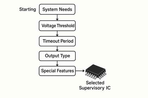
Select a supervisory IC by defining your system's needs first. Key parameters include the voltage threshold, timeout period, output type, and special features like a windowed watchdog function.
This table breaks down the primary selection criteria:
| Parameter | Description | Key Considerations & Typical Values |
|---|---|---|
| Reset Threshold (\(V_{IT}\)) | The supply voltage at which reset is asserted. | Must be > \(V_{min}\) and < \(V_{DD\_min}\). E.g., 2.93V or 3.08V for a 3.3V system. |
| Timeout Period (\(t_{WD}\)) | The maximum time allowed between watchdog kicks. | \(\approx 2 \times\) the main loop's worst-case execution time. Typically 1.6s. |
| Reset Output | How the reset pin drives the line. | Open-Drain: More flexible, can be shared, requires an external pull-up. Push-Pull: Simpler, cannot be shared. |
| Watchdog Type | The logic used to detect a fault. | Standard: Resets on timeout only. Windowed: Resets on timeout OR if kicked too frequently. (Safer) |
| Reset Duration (\(t_{RP}\)) | The minimum time the reset pin stays asserted. | Must be longer than the MCU's minimum required reset pulse. Typically \(>140\text{ms}\). |
Does An External Watchdog Timer Require Its Own Independent Clock Source?
You're trying to minimize component count and cost. It might be tempting to think you could drive an external watchdog from an MCU's clock output pin. This would be a fundamental mistake that undermines the entire purpose of using one.
Yes, an external watchdog must have its own independent clock source. This is the core principle that makes it a reliable supervisor. All reputable watchdog ICs have a built-in, factory-trimmed RC oscillator that is completely separate from any MCU clock.
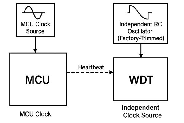
The Core Principle: An Independent Clock Source
The reason for this is to protect against common-mode failures. One of the most common reasons an MCU freezes is a failure of its clock source. The main crystal could fail to start, a solder joint could crack, or the internal PLL could lose lock. If the watchdog relied on that same clock source, it would also stop working at the exact moment it was needed most.
Clock Accuracy vs. Oscillation Robustness
The internal oscillator in a watchdog IC is not designed for high precision. Its accuracy might only be \(\pm 15\%\) over the full temperature range. A 1.6-second nominal timeout might vary between 1.36s and 1.84s. This is perfectly acceptable for supervising a software loop. Its design is optimized for guaranteed startup and continued oscillation under all specified operating conditions, not for frequency accuracy.
Real-World Example: Clock Failure in a High-Vibration Environment
In one high-vibration industrial environment, a solder joint on the main crystal fractured. The MCU locked up solid. The external watchdog, humming along on its own internal clock, correctly identified the lack of activity and reset the system. Without that independent clock, the unit would have been a silent brick.
What Are The Schematic Best Practices For Connecting An External WDT To An MCU?
You've selected the perfect watchdog IC. Now you have to integrate it into your schematic. A few simple connection errors can render your watchdog useless or, almost worse, cause constant, hard-to-debug nuisance resets.
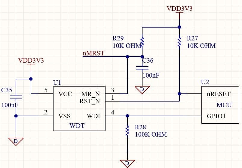
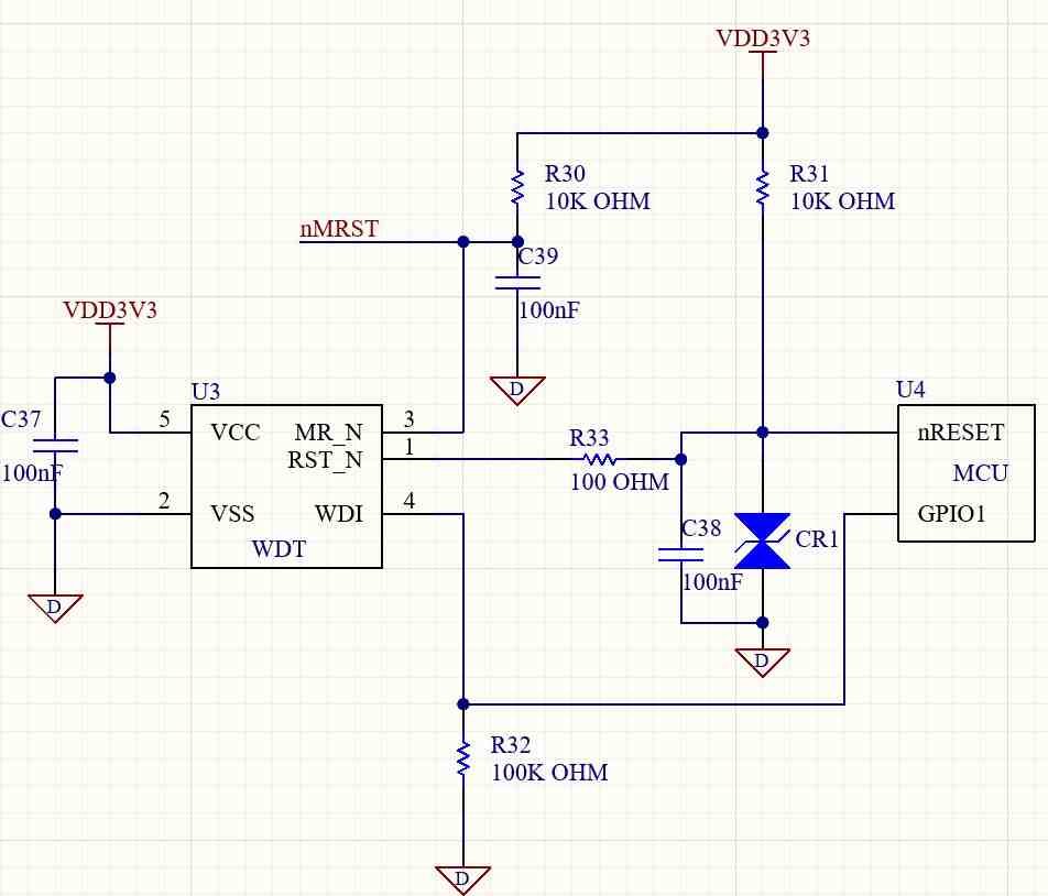
Connect the WDT's VCC to the rail it needs to monitor, with a dedicated 0.1µF decoupling capacitor. Connect its open-drain reset output to the MCU's nRESET pin with a pull-up resistor. Finally, connect the watchdog input (WDI) to an MCU GPIO.
This table summarizes the essential connections:
| Pin Name(s) | Connection Target | Required Components | Purpose & Key Considerations |
|---|---|---|---|
VCC | System Voltage Rail (e.g., 3.3V) | 0.1µF Ceramic Capacitor | Powers the IC and provides the voltage sense input. Place cap as close as possible. |
GND | System Ground Plane | Direct connection | Provides the ground reference for the IC. |
nRESET / RESET | MCU Reset Pin | 10 kΩ Pull-up Resistor | Asserts the reset signal on the MCU. Open-drain output allows sharing the line. |
WDI | MCU GPIO Pin | 100 kΩ Pull-down Resistor | Receives the "kick" signal from the MCU. Pull-down prevents false kicks at boot. |
MR | Manual Reset Button/Switch | 10 kΩ Pull-up, 0.1µF Debounce Cap | Allows a user or external system to trigger a manual reset. |
What Are The PCB Layout Guidelines For Watchdog Timer Circuits?
Your schematic is perfect. But a robust watchdog circuit can be completely undermined by a poor PCB layout. If noise gets into the circuit, you can experience phantom resets that are a nightmare to debug in the lab, let alone in the field.
Place the watchdog IC as close as possible to the microcontroller. The decoupling capacitor must be placed immediately next to the WDT's power and ground pins. Keep the trace connecting the WDT's reset output to the MCU's reset input short and direct.
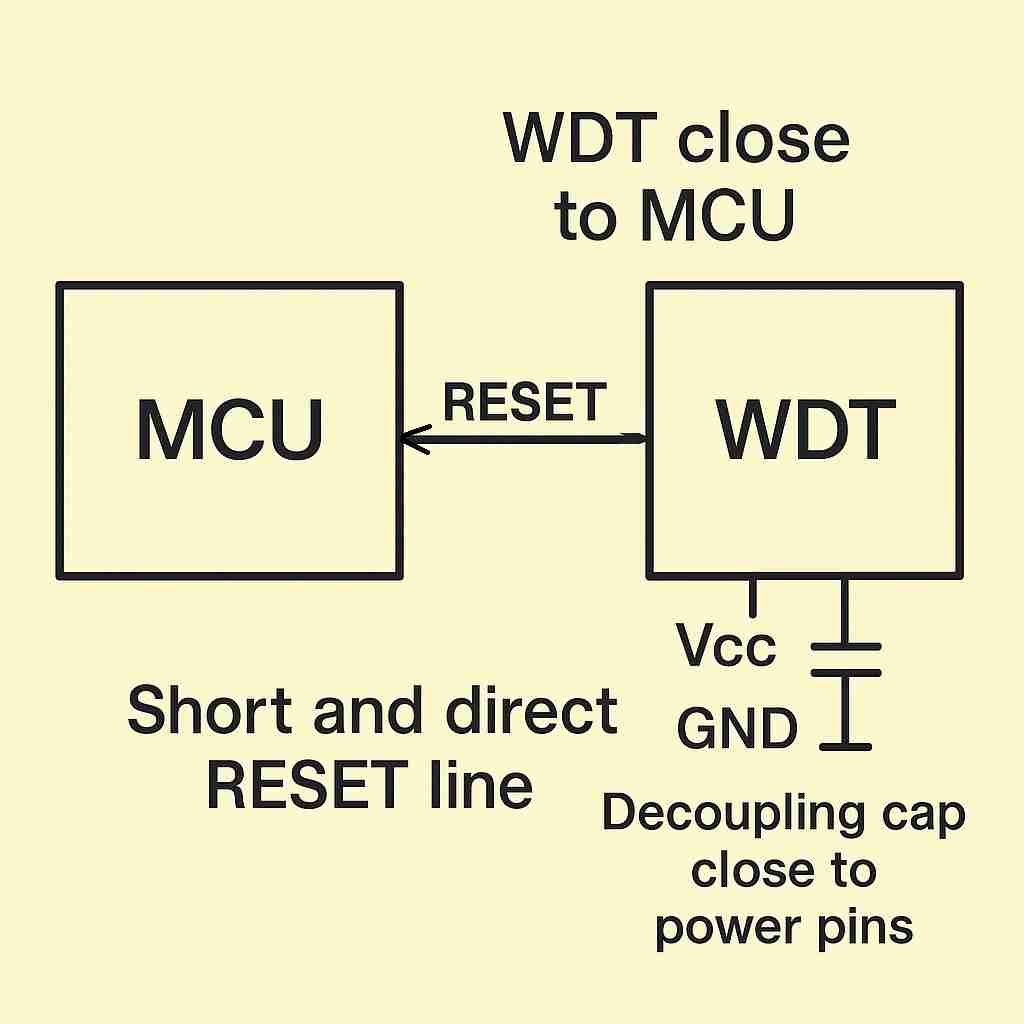
Guideline 1: Prioritize Proximity in Component Placement
Proximity is key. The WDT IC should be placed within 1-2 cm of the MCU. Place the 0.1 µF decoupling capacitor first, positioning it to minimize the distance from its pads to the IC's VCC and GND pins. This minimizes the inductance of the decoupling loop.
Guideline 2: Optimize the Decoupling Capacitor's Layout
The connection path should be: Power Plane/Trace -> Capacitor Pad -> VCC Pin. The capacitor's ground pad should have a via placed directly on the pad or immediately adjacent to it, providing a short, low-inductance path to the main ground plane. Use at least a 10 mil trace for these connections.
Guideline 3: Maintain a Solid and Uninterrupted Ground Plane
Use an uninterrupted ground plane directly under the watchdog IC and the MCU. This provides a low-impedance path for return currents and acts as a shield, dramatically improving noise immunity. Ensure there are no splits or high-current traces in the ground plane under this sensitive area.
Guideline 4: Route Sensitive Traces with Care
The RESET and WDI traces should be as short and direct as possible. Avoid running them parallel to high-speed signals. If you must cross a noisy trace, do so at a \(90^{\circ}\) angle on an adjacent layer to minimize capacitive coupling.
How Should A RESET Trace Be Routed On A PCB?
The RESET line is arguably one of the most sensitive traces on your board. While it's a low-speed signal, it's also asynchronous and level-sensitive. A small amount of noise—a glitch of just a few nanoseconds—can be misinterpreted as a valid reset command, causing your entire system to reboot.
The RESET trace must be kept as short as possible. Route it on an internal PCB layer, sandwiched between ground planes (a stripline configuration) to shield it from noise. Keep it far away from switching power supplies, clock lines, and board edges.
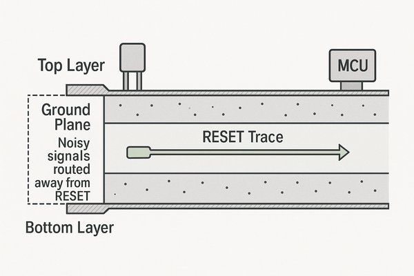
Reset Routing Rule 1: Control the Signal's Return Path
For every signal, there is a return current. For high-frequency noise coupled onto the line, the return current follows the path of least inductance (directly under the trace). Route the RESET trace over a continuous ground plane to ensure a clean, unbroken return path for any noise, preventing it from radiating.
Reset Routing Rule 2: Maintain Clearance from Noisy Traces
My rule of thumb is to maintain a clearance of at least \(3 \times\) the trace width (e.g., 15 mils for a 5 mil trace) from any high-frequency digital signal. For high-current switching nodes of a power supply, I increase this to 50-100 mils.
Reset Routing Rule 3: Use Internal Layers for Shielding
For 4-layer or higher boards, routing the RESET line on an inner layer between two solid ground planes is the best practice. This creates a stripline, which provides excellent shielding from external EMI.
Reset Routing Rule 4: Optimize Pull-Up Resistor Placement
The 10 kΩ pull-up resistor on an nRESET line should be placed closer to the MCU's RESET pin, not the source (WDT). This ensures the line is held strongly at a high logic level right at the most sensitive input pin.
Reset Routing Rule 5: Use Guard Traces for Maximum Noise Immunity
For exceptionally noisy environments, you can route a "guard trace" parallel to the RESET trace. This guard trace is connected to the ground plane with vias every 50-100 mils, a technique known as "via stitching7," which creates an effective shield.
How Are Watchdog Timer Circuits Protected From EMI And ESD Events?
Your product will eventually face the real world, which is full of electrostatic discharge (ESD) and electromagnetic interference (EMI). The RESET line is a prime target for these events, which must be mitigated to pass standards like IEC 61000-4-2 (ESD) and IEC 61000-4-4 (EFT).
Protect watchdog circuits from EMI and ESD by adding a low-capacitance transient voltage suppression (TVS) diode on any exposed reset lines, and by implementing a small RC low-pass filter directly at the MCU's reset pin to filter out high-frequency noise.
This table summarizes common protection strategies:
| Threat | Relevant Standard | Protection Method | Placement & Component Choice |
|---|---|---|---|
| ESD | IEC 61000-4-2 | TVS Diode | At the connector/button. Use low-capacitance (\(<10 \text{ pF}\)) type. |
| EFT / Burst | IEC 61000-4-4 | RC Low-Pass Filter | At the sensitive MCU pin. \(R=100\Omega\), \(C=100\text{pF}\) is a typical starting point. |
| Radiated EMI | IEC 61000-4-3 | Ground Plane Shielding / Ferrite Bead8 | Solid ground plane under the circuit. Bead is placed in series with the trace, close to the noise source or victim. |
How Does A Watchdog Timer Affect The Power Budget In A Low-Power Design?
In a battery-powered IoT device, every microamp counts. Adding another active component like an external watchdog seems like it would be a step in the wrong direction, potentially reducing battery life. This is a common concern, but modern components are designed to address it.
Modern nano-power watchdog timers have a minimal impact on the power budget, often consuming only a few microamps (µA) or even nanoamps (nA). For example, a timer like the Texas Instruments TPL5010 consumes just 35 nA, making its contribution to the overall power budget negligible.
Examining Datasheet Power Consumption
This table shows a few examples of low-power supervisors:
| Part Number | Manufacturer | Typical Current Consumption |
|---|---|---|
| TPL5010 | Texas Instruments | 35 nA |
| MAX16161 | Analog Devices | 825 nA |
| STM6779 | STMicroelectronics | ~3 µA |
Performing a Quantitative Power Budget Analysis
Consider a device that sleeps for 599s at 3µA and is active for 1s at 10mA. The total charge consumed per cycle is \((599\text{s} \times 3\text{µA}) + (1\text{s} \times 10\text{mA}) \approx 11.8 \text{ mC}\). Adding an 825nA watchdog increases the sleep current to 3.825µA. The new charge consumed is \((599\text{s} \times 3.825\text{µA}) + (1\text{s} \times 10\text{mA}) \approx 12.3 \text{ mC}\). This is a ~4% increase in total consumption—a small price for vastly improved reliability.
Using an External Watchdog as a Power-Saving Tool
In some designs, an external watchdog can actually save power. You can use a nano-power WDT like the TPL5010 as the primary system wake-up timer. The MCU can go into its absolute lowest power state (\(<1 \text{ µA}\)) and rely on the external watchdog to send it a wake-up signal, resulting in a lower average system current than using the MCU's own internal low-power timer.
How Is The Watchdog Timer Functionality Hardware-Tested During Board Bring-up?
You have your first prototype boards back from the fab. You've designed in a watchdog circuit, but you can't just assume it works. You must perform specific tests to verify its functionality. Skipping this step is a recipe for discovering the problem after you've shipped thousands of units.
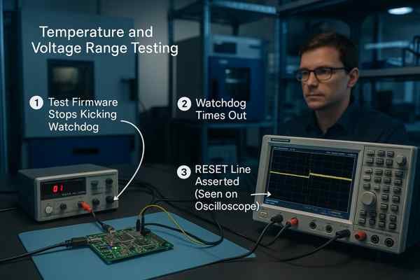
To test a watchdog, you must write test firmware that intentionally stops kicking the watchdog and then use an oscilloscope to verify that the RESET line is correctly asserted after the specified timeout period. This validation must be performed across the operating temperature and voltage range.
This table outlines a formal test plan:
| Test Name | Procedure | Expected Outcome & Verification |
|---|---|---|
| Baseline Operation | Run firmware that correctly kicks the WDT in a loop. | System runs indefinitely. nRESET pin remains high. Verified with oscilloscope. |
| Timeout Validation | In firmware, stop kicking the WDT after an initial period. | nRESET asserts low after the specified timeout (\(t_{WD}\)). Verified with oscilloscope. |
| Brown-Out Reset (BOR)9 | Slowly decrease VCC with a programmable power supply. | nRESET asserts when VCC crosses the IC's voltage threshold (\(V_{IT}\)). Verified with oscilloscope & DMM. |
| Windowed WDT (Fast Kick) | If applicable. Kick the WDT in a tight loop, faster than the minimum window. | nRESET asserts due to a window violation. Verified with oscilloscope. |
| Manual Reset (MR) | Press the manual reset button. | nRESET asserts. Check for switch bounce on the oscilloscope. |
Conclusion
A watchdog timer is a fundamental building block of a reliable product. While an MCU's internal watchdog is better than nothing, an external supervisory IC provides a far more robust, verifiable, and safety-compliant solution. Proper selection, meticulous schematic design, and careful layout are essential to making it work when it matters most.
-
Understanding IEC 60601-1 is crucial for compliance in medical device design, ensuring safety and effectiveness. ↩
-
Learn how IEC 62304 sets the standard for safe medical device software, ensuring compliance and reducing risk in critical healthcare applications. ↩
-
Learn how latch-up events can compromise microcontroller reliability and why external watchdog timers are crucial for robust system protection. ↩
-
Learn about IEC 61508 to grasp its significance in ensuring safety and compliance in industrial applications. ↩
-
Learn how ISO 26262 sets the benchmark for automotive functional safety, ensuring your designs meet industry standards for risk management and reliability. ↩
-
Learn how DO-178C/DO-254 standards ensure software and hardware safety in avionics, crucial for compliance and risk management in critical systems. ↩
-
Learn how via stitching shields sensitive traces like RESET lines, reducing EMI and improving circuit reliability in noisy environments. ↩
-
Learn how ferrite beads help reduce electromagnetic interference (EMI) in circuits and why their placement is crucial for effective noise suppression. ↩
-
Exploring BOR helps in designing systems that maintain stability during power fluctuations. ↩


