 Skip to content
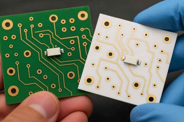
High-frequency designs often struggle with signal loss. This degrades performance, limiting what your circuits can achieve. Teflon PCBs offer a powerful solution to this common engineering headache.
Teflon PCBs, made with Polytetrafluoroethylene (PTFE), offer exceptionally low dielectric loss and a stable dielectric constant at high frequencies. This makes them ideal for RF, microwave, and high-speed digital applications, ensuring superior signal integrity where other materials falter.
When I first encountered Teflon PCBs, I was working on a demanding aerospace project. The signal integrity requirements were unlike anything I'd seen with standard FR-4. It quickly became clear why these specialized materials exist. If you're pushing the boundaries of frequency or need your signals to be incredibly clean, understanding Teflon is key. Let's dive into what makes these boards special and when you should consider them.
What is the Teflon material in PCB?
Struggling to understand what "Teflon" means for circuit boards? It's more than just a non-stick coating. This material offers unique electrical properties for demanding electronics.
"Teflon" in PCBs refers to Polytetrafluoroethylene (PTFE), a synthetic fluoropolymer. It's chosen for its excellent dielectric properties, particularly low signal loss and a stable dielectric constant, especially at high frequencies, making it a prime material for specialized circuit boards.
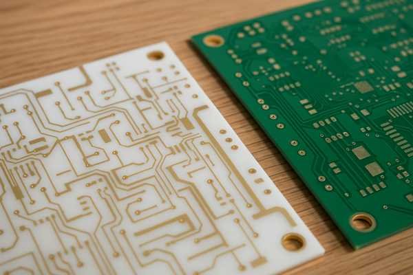
When we talk about "Teflon" in the context of printed circuit boards, we are generally referring to Polytetrafluoroethylene1, or PTFE. This is a fluoropolymer, a type of plastic known for its slipperiness – think non-stick pans. But for us engineers, its electrical characteristics are far more interesting. Pure PTFE itself is quite soft, so in PCB applications, it's often reinforced with woven glass, ceramic fillers, or other materials to create a rigid laminate. These fillers also help to tailor its mechanical and electrical properties, like the dielectric constant2 or thermal expansion. For instance, I've worked with laminates from Rogers Corporation3, like their RT/duroid® series, or materials from Taconic, which are well-known PTFE-based composites. These are not just pure PTFE sheets; they are engineered materials.
Here's a look at common compositions:
| Laminate Type | Base Polymer | Typical Reinforcement/Filler | Key Characteristic Focus |
|---|---|---|---|
| Low Dk PTFE Laminates | PTFE | Glass Microfibers, Woven Glass | Lowest Dielectric Constant/Loss |
| Ceramic-Filled PTFE | PTFE | Ceramic Powders | Controlled Dk, Improved CTE |
| High Dk PTFE Laminates | PTFE | High Dk Ceramic Powders | Circuit Miniaturization |
The key takeaway is that PTFE forms the core dielectric material that gives these PCBs their high-performance edge, especially when signals start moving really, really fast, often in the GHz range.
What are the advantages of Teflon?
Wondering why engineers choose Teflon for critical applications? Its benefits go beyond just high frequency. This material offers a unique combination of properties.
Teflon (PTFE) provides exceptionally low dielectric loss, a stable dielectric constant over frequency and temperature, high chemical resistance, and a wide operating temperature range. These advantages ensure superior signal integrity and reliability in demanding environments.
The advantages of using Teflon, or more accurately PTFE-based laminates, in PCBs are quite significant, especially for certain types of applications. I've seen these benefits make or break a design in high-stakes projects.
Key Advantages and Their Impact
| Advantage | Description | Impact on Design | Example Value (Typical) |
|---|---|---|---|
| Low Dielectric Loss (Df)4 | Minimal signal energy absorbed by the material. | Higher signal power, better signal-to-noise ratio, especially at high frequencies. | Df ~0.0009 - 0.0027 @ 10 GHz (e.g., Rogers RT/duroid 5880, RO3000 series) |
| Stable Dielectric Constant (Dk) | Dk remains consistent over a wide range of frequencies and temperatures. | Predictable impedance, reliable performance for filters and matching networks. | Dk ~2.2 - 3.5 for many RF types (e.g., Rogers RT/duroid 5880 Dk 2.2) |
| Excellent Chemical Resistance5 | Inert to most solvents, acids, and bases. | Durability in harsh chemical environments, suitable for industrial or medical sensors. | Resistant to common industrial chemicals. |
| Wide Operating Temp. Range | Maintains properties from cryogenic up to high temperatures. | Usable in extreme environments, from space applications to high-power systems. | Approx. -200°C to +260°C (pure PTFE) |
| Low Moisture Absorption | Absorbs very little water. | Consistent electrical performance in humid conditions, prevents Dk drift. | < 0.01% (ASTM D570 for pure PTFE) |
This combination makes PTFE laminates not just "usable" but often "excellent," particularly when my insight about needing ultimate signal integrity comes into play for applications like millimeter-wave radar or 5G/6G systems. The low loss at tens of GHz is something standard materials just can't touch.
Which material is best for PCB board?
Choosing the right PCB material feels overwhelming with so many options. Is there one "best" material? The answer often depends on your specific project needs.
There's no single "best" PCB material; the optimal choice depends on application requirements like frequency, temperature, cost, and mechanical stress. Teflon (PTFE) excels for high-frequency, while FR-4 is great for general-purpose, cost-sensitive designs.
This question, "Which material is best?", is one I hear a lot. And the honest answer is: it depends entirely on what you're trying to do. There's no universal "best." It's about finding the best fit for your specific application's performance requirements and budget.
For High Frequency & Critical Signals: Teflon (PTFE) Composites
If your design involves very high frequencies (think GHz range), sensitive analog signals, or requires extremely stable impedance, then PTFE-based laminates are often the top contenders. My experience with millimeter-wave radar systems and some high-speed data communication links confirms this. The low loss and stable dielectric constant are hard to beat.
For General Purpose & Cost-Sensitive: FR-4
FR-4, a glass-reinforced epoxy laminate, is the workhorse of the electronics industry. It's relatively inexpensive, easy to manufacture, and offers decent electrical and mechanical properties for a vast range of applications – from consumer electronics to many industrial controls. If your frequencies are below 1 GHz and your signal integrity requirements aren't extreme, FR-4 is usually the most economical and practical choice.
Other Specialized Materials
Beyond these two, there are others like Polyimide6 for flex or high-temp, CEM for low-cost, or Metal Core PCBs for thermal management.
Here's a simplified comparison table:
| Feature | PTFE Composites (e.g., RT/duroid 5880) | FR-4 (Standard) | Polyimide (Rigid/Flex) | MCPCB (Aluminum Base) |
|---|---|---|---|---|
| Typical Max Freq. | Very High (10s-100s GHz) | Moderate (Up to ~1-3 GHz) | Moderate / High (Flex dep.) | Low (Power, not RF focus) |
| Dk @ 1 GHz | ~2.2 - 3.5 (stable) | ~4.0 - 4.8 (varies) | ~3.2 - 4.5 | N/A (focus on thermal) |
| Df @ 1 GHz | Very Low (~0.0009 - 0.002) | Moderate (~0.015 - 0.025) | Moderate (~0.005 - 0.015) | N/A (focus on thermal) |
| Cost Index (FR-4=1) | 5x - 20x | 1x | 2x - 10x | 2x - 5x |
| Thermal Cond. (W/mK) | ~0.2 - 0.6 | ~0.25 - 0.35 | ~0.12 - 0.35 | High (1 - 3 for dielectric layer) |
| Manufacturability | More Complex | Standard | Moderate (Flex needs care) | Specialized (Metal Base) |
So, the "best" material is the one that meets your technical needs without over-engineering and blowing your budget. For a project I worked on involving a high-speed ADC evaluation board, the initial thought was FR-4, but the noise floor was too high. Switching to a PTFE-based material, though more expensive, brought the performance into spec.
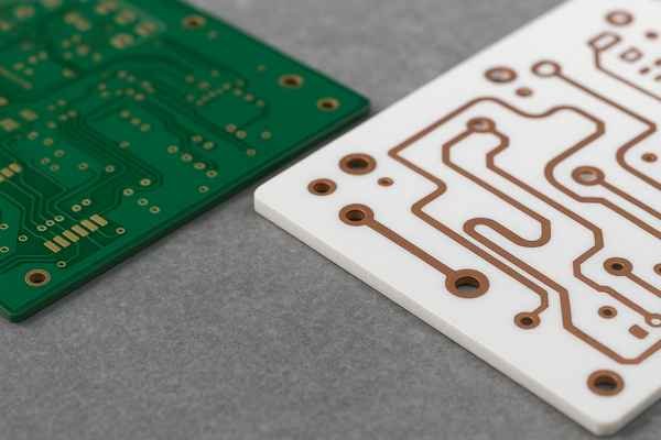
What is the difference between PTFE and FR4?
Confused about when to use PTFE versus the common FR-4? Understanding their key differences is crucial. This choice significantly impacts your circuit's performance and cost.
PTFE offers superior high-frequency performance with much lower dielectric loss and a more stable dielectric constant than FR-4. However, FR-4 is significantly cheaper and easier to manufacture, making it suitable for general-purpose applications.
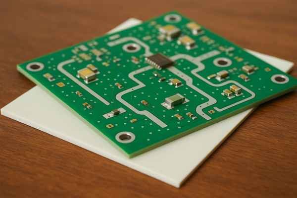
The differences between PTFE-based laminates and FR-4 are quite stark, and they dictate where each material shines. I've had to make this choice on countless projects, weighing performance against cost and manufacturability.
Electrical Performance: The Core Difference
The most significant divergence is in how they handle electrical signals, particularly at high frequencies.
| Property | PTFE-based Laminates (e.g., Rogers RT/duroid 5880) | FR-4 (Typical Standard Grade) |
|---|---|---|
| Dk (Dielectric Constant) | Low & Stable (e.g., 2.2 @ 10 GHz) | Higher & Variable (e.g., ~4.3 @ 1 GHz, can rise to 4.8) |
| Df (Dissipation Factor) | Very Low (e.g., 0.0009 @ 10 GHz) | Higher (e.g., ~0.02 @ 1 GHz, worsens with freq.) |
| Frequency Stability | Excellent | Fair to Poor (Dk/Df change with freq.) |
| Signal Attenuation (Loss)7 | Minimal, especially at >1 GHz | Significant at >1 GHz |
(Values for PTFE from Rogers Corp. datasheets, FR-4 values are typical industry ranges).
Other Key Differences
| Feature | PTFE-based Laminates | FR-4 |
|---|---|---|
| Max Use Temp. | Higher (e.g., some up to 260°C continuous) | Lower (Tg typically 130-180°C) |
| Moisture Absorption | Very Low (<0.02%) | Higher (0.1% - 0.25%) |
| Processing | Complex, specialized (drilling, PTH prep) | Standard, widely available, easier |
| Material Cost | High to Very High (5x - 20x FR-4) | Low |
| Chemical Resistance | Excellent | Good |
| Dimensional Stability | Good (with fillers), but needs careful handling | Generally Good, well-understood |
I remember a project where we tried to push FR-4 for a 5 GHz Wi-Fi application to save costs. The signal loss was just too high, and the impedance control was a nightmare due to Dk variations. Switching to a Rogers RO4000 series material (a hydrocarbon ceramic, but PTFE-like in performance for many RF uses) solved the problem instantly, albeit at a higher board cost. The lesson was clear: for high-frequency, choosing the right material upfront saves a lot of pain later.
What material is used in PCB for RF?
Designing an RF circuit and wondering about materials? Standard PCB materials often fall short. You need specific properties for optimal radio frequency performance.
PTFE-based laminates are predominantly used for RF PCBs due to their low dielectric loss, stable dielectric constant, and tight manufacturing tolerances. Materials from Rogers, Taconic, or Arlon are common choices for these demanding applications.
When you're working with Radio Frequency (RF) and microwave circuits, material selection is absolutely critical. The wrong material can kill your signal before it even gets to the antenna or from the antenna to your sensitive receiver.
Leading RF PCB Materials
The go-to materials for RF PCBs are overwhelmingly PTFE-based laminates or similar high-performance dielectrics. Companies like Rogers Corporation, Taconic, and Isola are key suppliers.
| Material Class | Manufacturer Example(s) | Series Example(s) | Typical Dk @ 10 GHz | Typical Df @ 10 GHz | Key Applications |
|---|---|---|---|---|---|
| PTFE / Woven Glass | Rogers Corporation | RT/duroid® 5870/5880 | 2.20 - 2.33 | 0.0009 - 0.0012 | High-Frequency, Low Loss, Antennas |
| Ceramic-Filled PTFE | Rogers Corporation | RO3000® Series (e.g., RO3003) | 3.00 - 10.2 | 0.0010 - 0.0027 | Power Amps, Filters, Couplers |
| Hydrocarbon Ceramic | Rogers Corporation | RO4000® Series (e.g., RO4350B) | 3.48 - 6.15 | 0.0021 - 0.0037 | Cost-Sensitive RF, Automotive Radar |
| PTFE / Woven Glass | Taconic | TLY Series (e.g., TLY-5) | 2.17 - 2.20 | 0.0009 | Millimeter-wave, Very Low Loss |
| Thermoset Microwave | Isola | Astra® MT77, I-Tera® MT40 | 3.00 - 3.60 | 0.0017 - 0.0031 | High-Speed Digital, RF |
(Data sourced from respective manufacturer datasheets. Dk and Df values are nominal and can vary slightly with test methods and specific grades.)
The primary reasons these materials are chosen for RF applications align with my core insight: they provide the extremely low dielectric loss and stable dielectric constant needed for ultimate signal integrity, especially as frequencies climb into the tens or even hundreds of GHz for applications like 5G/6G base stations or advanced driver-assistance systems (ADAS) radar. Using FR-4 for such applications would result in unacceptable signal degradation.
What are the disadvantages of Teflon material?
Teflon PCBs sound great for high performance, but are there downsides? Yes, cost and manufacturing complexity are significant. Understanding these helps make informed design choices.
The main disadvantages of Teflon (PTFE) PCBs are high material cost, difficult and specialized manufacturing processes (drilling, plating), and potentially lower dimensional stability compared to FR-4 if not properly engineered with fillers.
While Teflon (PTFE) based PCBs offer fantastic electrical performance, they aren't without their drawbacks. I've had to weigh these carefully in many project planning stages. It's not just about performance; practicality and cost always play a role.
Key Disadvantages of PTFE PCBs
| Disadvantage | Description & Implication | Typical Cost Impact (vs. FR-4) |
|---|---|---|
| High Material Cost8 | Raw PTFE resins and specialized laminate manufacturing are expensive. | 5x to 20x higher |
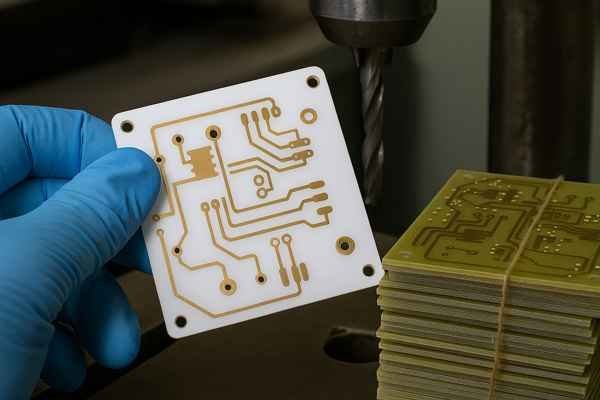
| Difficult Drilling | PTFE is soft and can smear, requiring special drill bits, speeds, and feeds. This increases processing time and cost. | Adds to fabrication cost |
| Challenging PTH Plating | Low surface energy requires chemical (e.g., sodium naphthalene etch) or plasma treatment for copper adhesion in vias. | Adds significant process steps |
| Dimensional Stability Issues | Higher CTE than FR-4, especially for unfilled PTFE. Fillers help, but care is needed for multilayer registration & via reliability. | Requires careful design & fab |
| Limited Supplier Base | Fewer fabricators have the expertise and equipment for PTFE, potentially affecting lead times and price competition. | Can increase lead time/cost |
| Processing Sensitivity | More sensitive to handling and processing parameters compared to robust FR-4. | Higher scrap rate if not handled well |
| Bonding Multilayers | Achieving strong, void-free bonds between PTFE layers in multilayer boards can be more complex than with FR-4 prepregs. | Requires specialized bondplies |
I recall a project where we specified a complex 8-layer PTFE board. The initial quotes were eye-watering, not just due to the material but also the tight tolerances and specialized via structures. We had to ensure the performance benefits truly justified this significant investment. For many applications, this cost-benefit analysis is crucial.
What is the temperature range of Teflon PCB?
Planning for extreme temperatures in your electronics? Teflon PCBs might be the answer. They handle a much wider temperature range than standard board materials.
Teflon (PTFE) PCBs can operate over a very wide temperature range, typically from cryogenic temperatures (around -200°C) up to a continuous maximum of about 260°C for pure PTFE. Specific laminates may have slightly different ranges based on fillers and adhesives.
The temperature range of Teflon PCBs is one of their significant advantages, making them suitable for environments where other materials would fail or perform erratically.
Temperature Performance Comparison
| Material Type | Typical Min. Operating Temp. (°C) | Typical Max. Continuous Operating Temp. (°C) | Glass Transition Temp. (Tg °C) | Notes |
|---|---|---|---|---|
| Pure PTFE | -200 to -260 | ~260 | ~120 (secondary), 327 (melt) | Exceptional range |
| PTFE Laminates | -70 to -200 (filler dependent) | 200 to 260 (laminate specific) | Varies with filler/resin | Check specific datasheet |
| FR-4 (Standard) | -40 to -50 | 105 to 130 | 130 - 140 | Limited high-temp |
| FR-4 (High Tg) | -40 to -50 | 150 to 170 | 170 - 180 | Better than standard FR-4 |
| Polyimide (Rigid) | -200 | 240 to 260 | >250 | Good high-temp, can be costly |
(Values are general; always consult manufacturer datasheets for specific materials. Source: Various material handbooks and supplier data like Rogers Corp., Isola.)
Pure PTFE's crystalline melting point is around 327°C, but continuous use is recommended up to 260°C. The fillers in PTFE laminates can influence these ranges slightly, particularly how well mechanical properties are retained. For example, some ceramic-filled PTFE laminates are engineered to have a Coefficient of Thermal Expansion (CTE) that better matches copper across this wide temperature range, which is crucial for the reliability of plated through-holes during thermal cycling. My work in aerospace often involved components that saw significant temperature swings, making these PTFE-based materials essential.
What temperature is bad for Teflon?
Using Teflon in high-heat designs? It's crucial to know its limits. Exceeding certain temperatures can degrade Teflon, releasing harmful substances and compromising your PCB.
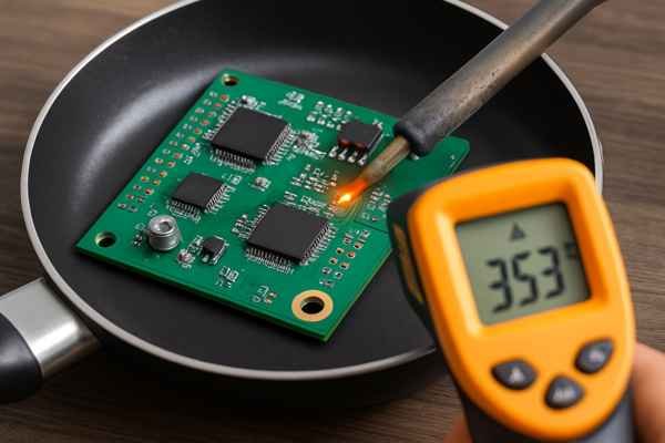
Temperatures consistently above 260°C (500°F) begin to degrade Teflon (PTFE). Significant decomposition, releasing toxic fumes, occurs above 350-400°C (662-752°F). Soldering temperatures are generally safe if applied correctly and for short durations.
While Teflon (PTFE) has a high continuous use temperature, there are definitely temperatures that are "bad" for it, leading to degradation or decomposition. Understanding these limits is important for both manufacturing and the end-use application of Teflon PCBs.
PTFE Degradation Thresholds
| Temperature Range (°C) | Temperature Range (°F) | Effect on PTFE | Key Concern(s) |
|---|---|---|---|
| Up to 260°C | Up to 500°F | Generally safe for continuous use. | Normal operating range for most PTFE grades. |
| 260°C - 350°C | 500°F - 662°F | Accelerated degradation, slight outgassing, potential mechanical property reduction. | Reduced lifespan, minor fume release. |
| Above 350°C (approaching 400°C) | Above 662°F (approaching 752°F) | Significant thermal decomposition9 begins, release of toxic fluorocarbon fumes. | Polymer fume fever risk, hazardous byproduct generation. |
| >400°C | >752°F | Rapid decomposition, severe fume release, charring, loss of material integrity. | High toxicity risk, material destruction. |
(Source: Safety data from fluoropolymer manufacturers like Chemours, and general polymer science literature.)
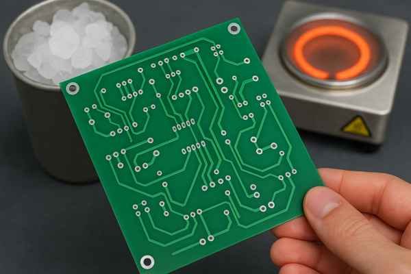
The critical point is that while soldering temperatures (e.g., lead-free peak reflow around 230-260°C) are within the safe short-term exposure for PTFE, prolonged or uncontrolled heating above 260°C is detrimental. Any process involving localized high heat, like manual rework or laser drilling, needs careful control and robust fume extraction systems. I’ve seen manufacturing floors where strict protocols are in place for any high-temperature processing of PTFE materials specifically because of these decomposition risks.
What happens if Teflon gets too hot?
Worried about overheating Teflon components in your design? Exceeding its thermal limits causes more than just poor performance. It can lead to material breakdown and safety hazards.
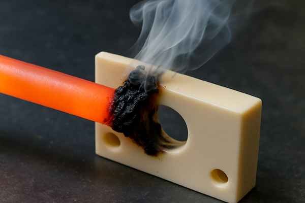
If Teflon (PTFE) gets too hot (significantly above 260°C), it begins to degrade. At higher temperatures (above 350-400°C), it decomposes, releasing potentially toxic and corrosive fluorocarbon fumes, and loses its structural and electrical integrity.
When Teflon (PTFE) gets too hot, a sequence of events occurs depending on how high the temperature goes and for how long. It's not like some plastics that simply melt into a puddle; PTFE behaves differently due to its unique chemical structure.
Stages of PTFE Overheating
| Temperature Stage | Approximate Range (°C / °F) | Observable Effects & Consequences |
|---|---|---|
| 1. Max Continuous Use Exceeded | >260°C to ~300°C / >500°F to ~572°F | Slight softening, minor outgassing of volatiles, accelerated aging, possible slight discoloration over time. |
| 2. Initial Decomposition (Moderate) | ~300°C to ~350°C / ~572°F to ~662°F | Increased outgassing, start of polymer chain scission, release of some fluorinated compounds. Mechanical properties may weaken. |
| 3. Significant Decomposition (Severe) | >350°C to ~450°C / >662°F to ~842°F | Rapid breakdown of PTFE structure. Release of toxic and corrosive fumes including TFE monomer, HF, PFIB. Visible fumes or smoke. |
| 4. Gross Decomposition / Pyrolysis | >450°C / >842°F | Vigorous fuming, charring, complete loss of structural and electrical integrity. |
(Sources: Primarily based on thermal degradation studies of PTFE, e.g., "Fluoropolymers Handbook" and safety guidelines from manufacturers.)
During my time at Honeywell, we had very strict protocols for any rework involving PTFE-insulated wires or components. Any sign of discoloration or unusual odor was an immediate stop-work and investigation, precisely because of the risks associated with these decomposition products, especially perfluoroisobutylene (PFIB)10, which is highly toxic even in small concentrations. In a PCB context, this means reflow profiles need to be precise, and manual soldering requires skilled operators and excellent fume extraction. The structural and electrical integrity loss at higher temperatures means the PCB will cease to function correctly, potentially leading to catastrophic failure of the electronic assembly.
What is the dielectric constant of PTFE PCB?
Designing high-frequency circuits and need precise material data? The dielectric constant of your PCB is critical. For PTFE, this value is key to its performance.
Pure PTFE has a very low dielectric constant (Dk) of around 2.05 to 2.1. PTFE-based PCB laminates, often containing fillers, typically have Dk values ranging from approximately 2.2 to 10.2 or higher, remaining very stable across frequency and temperature.
The dielectric constant (Dk), also symbolized as εr (epsilon relative), is a fundamental property for any PCB material, especially when dealing with high-frequency signals. For PTFE PCBs, the Dk is one of its most prized characteristics.
Pure PTFE Baseline and Laminate Variations
Pure, solid Polytetrafluoroethylene has a Dk around 2.05 to 2.1 (Source: Polymer handbooks, material supplier data like Chemours). This is very low. However, PCB laminates are composites.
Common PTFE PCB Laminates and Their Dk Values
| Manufacturer (Example) | Laminate Series (Example) | Reinforcement/Filler Type | Typical Dk @ 10 GHz | Df @ 10 GHz (Typical) | Notes |
|---|---|---|---|---|---|
| Rogers Corporation | RT/duroid® 5880 | Glass Microfiber | 2.20 ± 0.02 | 0.0009 | Very low Dk, excellent for high frequency |
| Rogers Corporation | RT/duroid® 6002 | Ceramic | 2.94 ± 0.04 | 0.0012 | Low loss, good stability |
| Rogers Corporation | RO3003™ | Ceramic | 3.00 ± 0.04 | 0.0010 | Excellent Dk stability over temperature |
| Rogers Corporation | RO3006™ | Ceramic | 6.15 ± 0.15 | 0.0020 | Higher Dk for circuit size reduction |
| Rogers Corporation | RO3010™ | Ceramic | 10.2 ± 0.30 | 0.0022 | Very high Dk for significant miniaturization |
| Taconic | TLY-5 | Woven Glass | 2.20 ± 0.02 | 0.0009 | Low Dk, low loss, dimensional stability |
| Taconic | RF-35 | Ceramic | 3.50 ± 0.05 | 0.0018 | Good all-around RF performance |
(All Dk values cited are nominal Process Dk values from respective manufacturer datasheets, typically measured at 10 GHz using methods like clamped stripline resonator test per IPC-TM-650 2.5.5.5.)
The critical advantage, as I highlighted in my insights, is not just the Dk value itself but its stability. For these high-quality PTFE laminates, the Dk remains very consistent across a wide frequency range11 (e.g., 1 GHz to 40 GHz or higher) and over the operational temperature range. This predictability is essential for designing filters, impedance-matched transmission lines, and antennas that perform as simulated. In contrast, the Dk of FR-4 can vary significantly with frequency, making precise high-frequency design much more challenging.
Conclusion
Teflon PCBs offer superior high-frequency performance due to low loss and stable Dk. While pricier and harder to make, they are essential for demanding RF and high-speed applications.
-
Explore this link to understand how Polytetrafluoroethylene enhances electronic applications with its unique properties. ↩
-
Learn about the significance of dielectric constant in PCBs and how it impacts performance in high-speed applications. ↩
-
Discover the innovative materials from Rogers Corporation that can elevate your PCB designs and performance. ↩
-
Explore how low dielectric loss enhances signal integrity, especially in high-frequency applications like 5G. ↩
-
Discover materials with superior chemical resistance, ideal for harsh environments in industrial settings. ↩
-
Discover how Polyimide enhances flexible circuit designs with its high-temperature resistance and mechanical properties. ↩
-
Learn about the factors contributing to signal attenuation and strategies to minimize it for better performance in your designs. ↩
-
Understanding the high material costs can help in budgeting and decision-making for PCB projects. ↩
-
Understanding thermal decomposition effects is crucial for safe handling and processing of materials like PTFE, ensuring safety and efficiency in manufacturing. ↩
-
Understanding PFIB's health risks is essential for safety in environments where PTFE is used, especially in electronics. ↩
-
Dk consistency is vital for reliable PCB performance across frequencies. Learn more about its impact on design and functionality. ↩


