 Skip to content
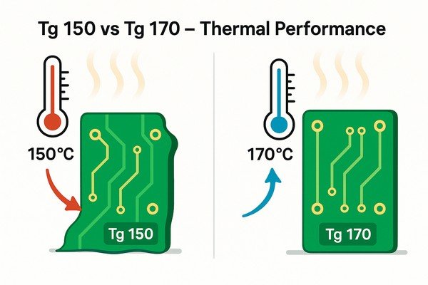
Choosing the right PCB material feels complicated. You see terms like Tg 150 and Tg 170, but what’s the real difference? Pick the wrong one, and your board could fail during assembly or in the field.
The main difference is thermal performance. A Tg 170 material withstands higher temperatures than a Tg 150 material before it starts to soften. This makes Tg 170 more reliable for lead-free soldering processes and high-temperature applications, providing a greater safety margin against board failure.
I've worked on dozens of projects, from medical devices to aerospace systems, and choosing the right material is one of the first critical decisions. It's not just about a number on a datasheet; it's about ensuring the product survives manufacturing and performs reliably for years. Let's move beyond simple definitions and into the practical engineering trade-offs that determine a product's success or failure.
What is Glass Transition Temperature (\(T_{g}\)) in PCBs?
You see "\(T_{g}\)" on every laminate datasheet, but what does it really mean? If you don't understand it, you risk choosing a material that can't handle the heat of assembly, leading to costly failures.
The Glass Transition Temperature (\(T_{g}\)) is the specific temperature at which a PCB's epoxy resin matrix transitions from a hard, rigid, "glassy" state to a softer, more flexible, "rubbery" state. It is a key indicator of a material's thermal stability.
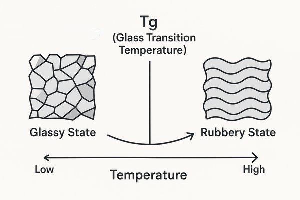
To understand this better, think about the FR-4 material itself. It's a composite made of woven fiberglass cloth impregnated with an epoxy resin binder. Below the \(T_{g}\), the polymer chains in the resin are locked in place, making the material hard and rigid.
The Polymer Science Behind Glass Transition
The epoxy resins used in PCBs are amorphous polymers. A key property that changes is the elastic modulus, or stiffness. Below its \(T_{g}\), an FR-4 laminate might have a modulus of around \(\approx 25 \text{ GPa}\). Above its \(T_{g}\), this can plummet by a factor of 10 or more, down to less than \(<2 \text{ GPa}\). This is why the board loses its structural integrity. This change is physical, not chemical, and it is reversible. The \(T_{g}\) is typically measured using methods like Thermomechanical Analysis (TMA)1 or Differential Scanning Calorimetry (DSC)2, as defined by the IPC-TM-6503 test standards.
| Property | Below \(T_{g}\) (Glassy State) | Above \(T_{g}\) (Rubbery State) |
|---|---|---|
| Polymer Chains | Tightly locked, minimal movement | Can slide past one another |
| Mechanical State | Hard, rigid, brittle | Soft, flexible, pliable |
| Elastic Modulus | High (\(\approx 25 \text{ GPa}\)) | Low (\(<2 \text{ GPa}\)) |
| Adhesion Strength | High | Significantly Reduced |
| Thermal Expansion | Lower, more controlled rate | Higher, accelerated rate |
Distinguishing \(T_{g}\) from a True Melting Point
It's a common misconception to equate \(T_{g}\) with a melting point. Melting is a phase transition from solid to liquid. A PCB does not melt at its \(T_{g}\); it just gets soft. The temperature at which the material is actually destroyed by heat is called the Decomposition Temperature (\(T_{d}\))4, which is much higher. For a high-Tg material, the \(T_{d}\) can be over \(340^{\circ}\text{C}\), whereas its \(T_{g}\) is \(170^{\circ}\text{C}\).
Why is \(T_{g}\) an important property for PCB materials?
It's easy to overlook \(T_{g}\) when you're focused on layout and components. But ignoring this property can cause your board to warp, delaminate, or fail electrically during the soldering process. I'll explain why it's a critical spec.
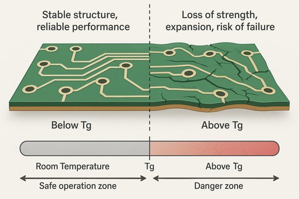
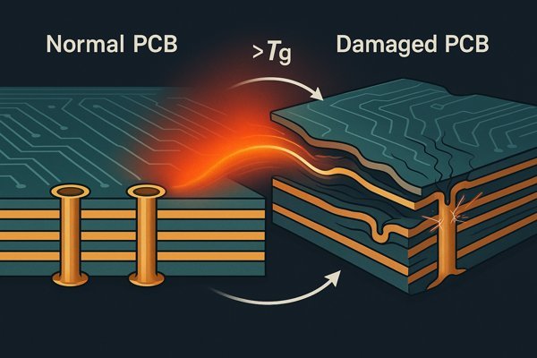
\(T_{g}\) is important because it defines the upper temperature limit for reliable PCB manufacturing and operation. Above its \(T_{g}\), a material's physical properties change drastically, leading to reduced mechanical strength, increased thermal expansion, and potential for immediate or long-term failure.
When a PCB operates above its \(T_{g}\), several dangerous things happen. I learned this the hard way on an industrial control project where intermittent failures were traced back to a localized hotspot pushing a standard-Tg board into its rubbery state during peak operation.
How Exceeding \(T_{g}\) Reduces Mechanical Strength
As the resin softens, its ability to act as a "glue" weakens considerably. The bond strength between the copper foil and the dielectric can drop by more than 50%. This makes the board highly susceptible to delamination and pad lifting, especially during the physical stress of rework.
How Thermal Expansion Above \(T_{g}\) Stresses Vias
The Z-axis CTE mismatch between the laminate and copper is a primary driver of PCB failure. For a typical high-Tg material, the Z-axis CTE below its \(T_{g}\) (\(\alpha_{1}\)) is around \(50 \text{ ppm}/^{\circ}\text{C}\). Above its \(T_{g}\), the Z-axis CTE (\(\alpha_{2}\)) can skyrocket to over \(250 \text{ ppm}/^{\circ}\text{C}\)—a 5-fold increase. Copper's CTE is only about \(17 \text{ ppm}/^{\circ}\text{C}\). This huge mismatch above the \(T_{g}\) creates immense tensile stress on via barrels, leading to cracking and failure.
| Property Change Above \(T_{g}\) | Consequence | Risk Level |
|---|---|---|
| Decreased Modulus | Board becomes soft and pliable | High |
| Increased Z-Axis CTE | High stress on vias, barrel cracking | Critical |
| Reduced Adhesion Strength | Pad lifting, delamination | High |
CAF Resistance and Long-Term Reliability
Another important factor is Conductive Anodic Filamentation (CAF)5 resistance. CAF is an electrochemical process where conductive filaments grow along the glass fibers, creating shorts between vias. High-Tg resin systems are generally more robust, offering superior resistance to CAF formation, especially in humid environments.
What is a standard \(T_{g}\) for FR-4 material?
"FR-4" is a broad term, not a single material. Using a "standard" FR-4 in a design that needs higher thermal performance is a common mistake that can lead to assembly failures. Let's clarify the different grades.
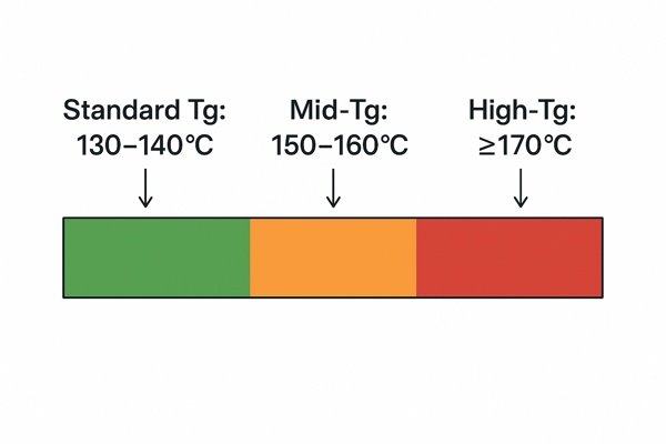
A standard FR-4 material has a \(T_{g}\) in the range of \(130^{\circ}\text{C}\) to \(140^{\circ}\text{C}\). Materials are further classified as mid-Tg (\(150^{\circ}\text{C}\) to \(160^{\circ}\text{C}\)) and high-Tg (\(\ge 170^{\circ}\text{C}\)). This classification helps engineers select the right grade for their application.
The specific material properties are defined by the IPC-4101, "Specification for Base Materials for Rigid and Multilayer Printed Boards."
Understanding Datasheets: \(T_{g}\) Ratings and Resin Systems
When I specify a material, I call out the IPC-41016 slash sheet (e.g., /126 for a common high-Tg material). It’s also important to understand that even with the same \(T_{g}\), different resin chemistries exist. Standard FR-4 often uses a dicyandiamide (DICY) curing agent. High-performance, high-Tg materials often use a phenolic-cured resin system, which results in a more tightly cross-linked polymer structure, improving the \(T_{d}\) and overall thermal stability.
| Material Class | Glass Transition Temp (\(T_{g}\)) | Common Applications | IPC-4101 Example Sheet |
|---|---|---|---|
| Standard Tg | \(130^{\circ}\text{C} - 140^{\circ}\text{C}\) | Consumer electronics, simple 2-layer boards | /21, /24 |
| Mid-Tg | \(150^{\circ}\text{C} - 160^{\circ}\text{C}\) | More complex multilayer boards, some lead-free | /99 |
| High-Tg | \(\ge 170^{\circ}\text{C}\) | Lead-free soldering, automotive, industrial | /126, /129 |
How does \(T_{g}\) affect PCB performance during lead-free soldering?
Lead-free soldering is now the law of the land, but it's much harder on PCBs. The higher temperatures can destroy a board made from the wrong material. Here's how a high \(T_{g}\) gives your design a fighting chance.
Lead-free soldering requires peak reflow temperatures of \(240^{\circ}\text{C} - 260^{\circ}\text{C}\), far exceeding a standard PCB's \(T_{g}\). A high-Tg material (e.g., with a \(T_{g} \ge 170^{\circ}\text{C}\)) provides a much larger thermal safety margin, keeping the board rigid and stable to prevent delamination and via failure during this intense process.
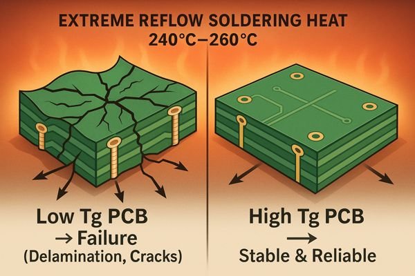
The entire thermal profile of the reflow process had to be elevated for lead-free alloys.
The Challenge of Multiple Reflow Cycles
A typical board with SMT components on both sides will pass through the reflow oven at least twice. If a BGA needs rework, the board might see localized heating four or five times. Each of these thermal excursions is a stress event. High-Tg materials, with their more robust resin systems, exhibit significantly better thermal endurance and are less likely to delaminate or suffer from via damage after the third or fourth heating cycle.
Calculating the Thermal Safety Margin for Soldering
The difference between the peak temperature and the material's \(T_{g}\) is a direct measure of how much thermal stress the board is under.
| Parameter | Standard FR-4 (\(T_{g} \approx 140^{\circ}\text{C}\)) | High-Tg FR-4 (\(T_{g} \ge 170^{\circ}\text{C}\)) |
|---|---|---|
| Peak Reflow Temperature | \(250^{\circ}\text{C}\) | \(250^{\circ}\text{C}\) |
| Material \(T_{g}\) | \(140^{\circ}\text{C}\) | \(170^{\circ}\text{C}\) |
| Temperature Above \(T_{g}\) (\(T_{peak} - T_{g}\)) | \(110^{\circ}\text{C}\) | \(80^{\circ}\text{C}\) |
That \(30^{\circ}\text{C}\) difference is huge. It's the difference between a board that reliably survives manufacturing and one that might suffer from hidden micro-cracks in vias, only to fail intermittently months later.
How to select the appropriate \(T_{g}\) rating for a PCB design?
Choosing between different \(T_{g}\) ratings can feel like a guess. Over-specifying wastes money, but under-specifying can lead to total product failure. Here’s a practical guide to making the right decision every time.
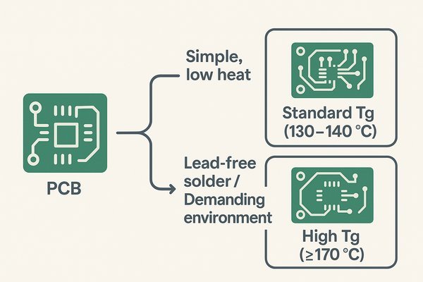
Select your \(T_{g}\) rating based on the assembly process, operating environment, and board complexity. For simple boards not subject to high heat, a standard \(T_{g}\) (\(130^{\circ}\text{C} - 140^{\circ}\text{C}\)) is sufficient. For any design using lead-free solder or operating in a demanding environment, choose a high-Tg material (with a \(T_{g} \ge 170^{\circ}\text{C}\)).
This detailed checklist can guide your selection process.
| Design Consideration | Use Standard-\(T_{g}\) (\(\approx 140^{\circ}\text{C}-150^{\circ}\text{C}\)) if... | Use High-\(T_{g}\) (\(\ge 170^{\circ}\text{C}\)) if... |
|---|---|---|
| Assembly Process | Using tin-lead solder or low-temp process. | Mandatory for lead-free assembly; multiple reflow cycles expected. |
| Operating Environment | Benign, room-temperature (e.g., office). | High ambient heat (e.g., automotive, industrial). |
| Max Operating Temp | Stays below \(< 115^{\circ}\text{C}\). | Will exceed \(> 120^{\circ}\text{C}\) (maintain \(>25^{\circ}\text{C}\) margin to \(T_{g}\)). |
| Layer Count | 2 to 6 layers. | 8 layers or more; board thickness \(> 2\text{mm}\). |
| Via Aspect Ratio | Low (\(< 8:1\)). | High (\(> 10:1\)); contains microvias. |
| Power Density | Low; minimal heat-generating components. | High; large FPGAs, processors, power modules. |
| Project Driver | Extreme cost-sensitivity is the #1 priority. | Long-term reliability is the #1 priority. |
Cost vs. Risk Analysis: A Financial Example
Imagine you're making 10,000 units. Using a high-Tg board adds $2.00 to the unit cost, for a total project increase of $20,000. Now assume that using a cheaper board leads to a 1% field failure rate. That's 100 failed units. If the cost of a single field return is $250, the total cost of failure is 100 * $250 = $25,000. In this realistic scenario, spending the extra $20,000 on better material would have saved the company $5,000, not to mention your brand's reputation.
When is it appropriate to use a high-Tg PCB?
You know high-Tg is better, but it costs more. So when is that extra cost truly justified? Using it unnecessarily can eat into your profit margins. I'll outline the specific scenarios where high-Tg is a must-have.
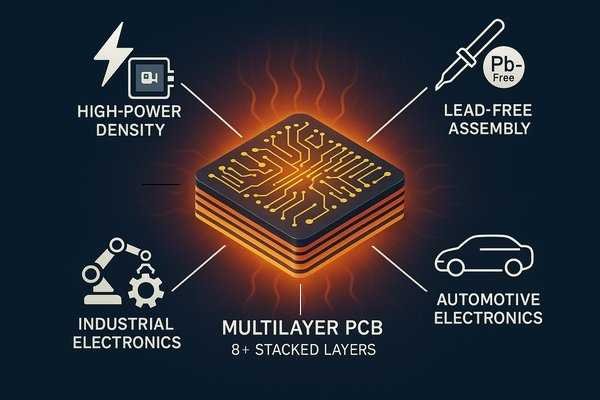
It is appropriate to use a high-Tg PCB (with a \(T_{g} \ge 170^{\circ}\text{C}\)) in applications requiring high reliability under thermal stress. This includes multilayer boards (>6-8 layers), products undergoing lead-free assembly, automotive and industrial electronics, and high-power density designs.
In my career, certain applications simply demand the robustness of high-Tg materials.
Thick Boards and High Aspect Ratio Vias
The via's "aspect ratio" is the ratio of the board thickness to the drilled hole diameter. For aspect ratios greater than \(> 10:1\) (e.g., a \(1.6\text{mm}\) thick board with a \(0.15\text{mm}\) drill), the via is a tall, thin cylinder highly susceptible to stress fractures. In these designs, using a high-Tg material with its lower Z-axis CTE is mandatory, not just recommended.
High-Temperature Operating Environments
Any product designed to operate consistently at elevated temperatures needs a high-Tg material. Automotive under-the-hood electronics, industrial control systems, and downhole drilling equipment all require materials that remain stable far above \(> 100^{\circ}\text{C}\).
Designs with High Power Density
Components like FPGAs, processors, and power MOSFETs can create significant localized hot spots. A high-Tg material not only withstands this temperature better but also tends to have slightly better thermal conductivity, helping to spread the heat.
What is the relationship between Glass Transition Temperature (\(T_{g}\)), Decomposition Temperature (\(T_{d}\)), and CTE?
\(T_{g}\) is the star of the show, but it doesn't tell the whole story. If you ignore \(T_{d}\) and CTE, you could still choose a material that fails under stress. Let's connect the dots between these critical thermal properties.
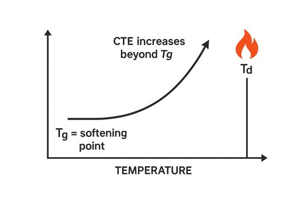
\(T_{g}\) is when the material softens, CTE is how much it expands with heat (and it gets worse above \(T_{g}\)), and \(T_{d}\) is when the material is permanently destroyed by heat. A reliable PCB material must have a high \(T_{g}\), a high \(T_{d}\), and a low CTE.
These parameters, along with thermal conductivity, define a material's true thermal performance.
\(T_{g}\): The Softening Point
As we've covered, this is the reversible softening point. A high \(T_{g}\) is the first requirement for a thermally robust material, as it defines the upper boundary of its optimal operating range.
\(T_{d}\): The Point of Destruction
This is the temperature at which the material's chemical bonds begin to break down, causing it to permanently degrade and lose mass. This is irreversible damage. A large window between \(T_{g}\) and \(T_{d}\) is a sign of a robust material.
CTE: The Stress Factor
The Coefficient of Thermal Expansion7 measures how much the material expands per degree of temperature change. A low Z-axis CTE is arguably as important as a high \(T_{g}\) for multilayer board reliability, as it directly impacts the stress on vias during thermal cycling.
T288: A Practical Durability Test
Time to Delamination (T288) is a practical, performance-based metric. It measures how long (in minutes) a material sample can be held at \(288^{\circ}\text{C}\) before the layers begin to separate. It's a great real-world test of a material's ability to survive the soldering process.
\(k\): The Heat Spreading Ability
Thermal Conductivity (\(k\))8 is the material's ability to conduct heat. While all FR-4 is relatively low, higher values help spread heat from hotspots.
| Property | Standard FR-4 (\(T_{g} \approx 140^{\circ}\text{C}\)) | High-Tg FR-4 (\(T_{g} \ge 170^{\circ}\text{C}\)) | What's Better? |
|---|---|---|---|
| \(T_{g}\) | \(\approx 140^{\circ}\text{C}\) | \(\ge 170^{\circ}\text{C}\) | Higher |
| \(T_{d}\) | \(\approx 305^{\circ}\text{C}\) | \(\ge 345^{\circ}\text{C}\) | Higher |
| Z-Axis CTE (\(\alpha_{1}\)) | \(\approx 60 \text{ ppm}/^{\circ}\text{C}\) | \(\approx 50 \text{ ppm}/^{\circ}\text{C}\) | Lower |
| Time to Delam (T288) | Fails quickly or not rated | \(> 10 \text{ minutes}\) | Higher |
| Thermal Conductivity (\(k\)) | \(\approx 0.3 \text{ W/m}\cdot\text{K}\) | \(\approx 0.4 \text{ W/m}\cdot\text{K}\) | Higher |
What happens to a PCB if its operating temperature exceeds its \(T_{g}\)?
So you ignored the warnings and the board got too hot. What's the worst that can happen? It's not just a minor glitch; exceeding the \(T_{g}\) can lead to catastrophic and often undetectable failures.
When a PCB's operating temperature exceeds its \(T_{g}\), the resin matrix softens, leading to a severe loss of mechanical strength. This results in delamination, board warping, and excessive Z-axis expansion that cracks vias, causing immediate or latent electrical failures.
The table below summarizes the grim reality of operating a board above its \(T_{g}\).
| Failure Mode | Root Cause (Physical Change) | Consequence for Product |
|---|---|---|
| Delamination | Reduced adhesion strength of the softened resin. | Catastrophic failure, board is scrap. |
| Via Barrel Cracking | Rapid Z-axis expansion (high CTE) stresses copper plating beyond its limit. | Intermittent or permanent open circuits. The "silent killer." |
| Warping & Twisting | Loss of mechanical stiffness (low modulus). | BGA solder joint failure, connector mating issues. |
| Pad Lifting | Weakened bond between copper foil and laminate. | Makes component placement and rework impossible. |
How Exceeding \(T_{g}\) Causes Invisible Via Failures
This is the failure mode that keeps experienced engineers up at night. When the board heats up past its \(T_{g}\), a via cracks. When it cools, the crack may close and pass all factory tests. In the field, the system only fails after it's been running for an hour and is fully heat-soaked. Once you power cycle it, the problem disappears. This is the kind of failure that will have your team chasing phantom software bugs for weeks.
How much more expensive is Tg 170 material compared to Tg 150?
You know high-Tg is technically superior, but you have to justify the cost to your manager. It's crucial to know the real numbers so you can make an informed business decision, not just an engineering one.
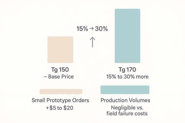
High-Tg 170 material is typically 15% to 30% more expensive than mid-Tg 150 material. For small prototype orders, this may only be a difference of $5 to $20. For production volumes, this incremental cost is often negligible compared to the total product cost and the high price of a field failure.
Here's a breakdown of how that cost difference might look in practice.
| Scenario | Board Specs | Approx. Cost w/ Tg 150 | Approx. Cost w/ Tg 170 | Cost Premium |
|---|---|---|---|---|
| Prototype | 4-Layer, \(100 \times 100\text{mm}\), 5 pcs | $45 | $55 | ~$2.00 / board (22%) |
| Production | 6-Layer, \(150 \times 100\text{mm}\), 100 pcs | $12.00 / board | $14.50 / board | ~$2.50 / board (21%) |
Factors That Increase the Cost Premium for High-Tg Materials
The 15-30% rule is a good guide, but the premium can sometimes be slightly higher for controlled impedance boards. To achieve a precise impedance (e.g., 50 ohms), the fabricator must use specific combinations of core and prepreg thicknesses. Fabricators need to stock a wider variety of these specific thicknesses in high-Tg material, and this increased inventory complexity can add a small amount to the overall cost premium.
What are common high-Tg laminate material names or manufacturers?
Asking your fabricator for "high-Tg FR-4" is a good start, but it's not specific enough. Knowing the key players and their flagship products allows you to have a much more precise conversation and ensure you get a quality material.
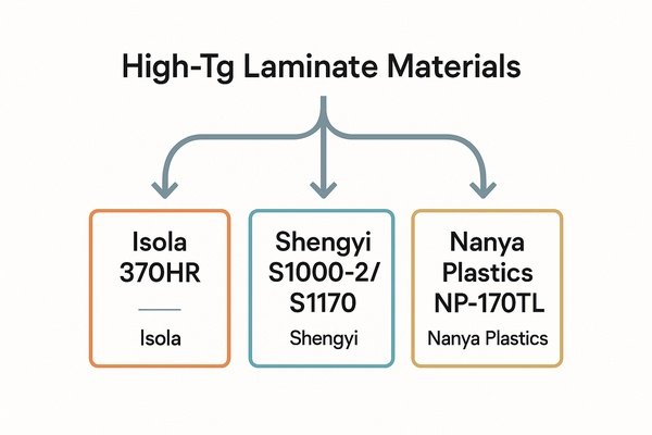
Some of the most common and reputable high-Tg laminate materials include Isola 370HR, Shengyi S1000-2/S1170, and Nanya Plastics NP-170TL. These are industry-standard choices offered by leading manufacturers and are widely stocked by PCB fabricators worldwide.
When specifying a material, it’s best to name a specific product or at least an equivalent.
| Manufacturer | High-Tg Material Series | Typical \(T_{g}\) | Key Features |
|---|---|---|---|
| Isola Group | 370HR, FR408HR | \(180^{\circ}\text{C}\) | Industry benchmark for high thermal performance. |
| Shengyi Technology | S1000-2, S1170 | \(175^{\circ}\text{C}\) | Very popular, cost-effective, great all-around choice. |
| Nanya Plastics | NP-170, NP-170TL | \(170^{\circ}\text{C}\) | Solid, reliable material known for processability. |
| Panasonic | Megtron Series | \(> 200^{\circ}\text{C}\) | Premium, very high-Tg and low-loss material for RF. |
How to Specify Material on Your Fab Notes
Your fabrication drawing is a contract with your manufacturer. Be specific. The best practice is to specify a preferred material and allow for a qualified equivalent:
'MATERIAL: LAMINATE AND PREPREG SHALL BE ISOLA 370HR OR EQUIVALENT. ALL MATERIALS MUST MEET OR EXCEED IPC-4101/126 SPECIFICATIONS. MINIMUM GLASS TRANSITION TEMPERATURE (\(T_{g}\)) SHALL BE \(170^{\circ}\text{C}\).'
A Warning About Unspecified Materials
When a quote from a supplier seems too good to be true, it often is. Some low-cost manufacturers may use generic, "no-name" laminates. While these might be marketed as "Tg 170," they often lack the batch-to-batch consistency and robustness of laminates from major brands. I always request a certificate of conformance for the laminate material lot used to build my boards to ensure traceability.
Conclusion
Ultimately, the choice between Tg 150 and Tg 170 is an investment in reliability. For a few extra dollars, a high-Tg material buys you a robust foundation, ensuring your design survives manufacturing and performs flawlessly in the hands of your customers.
-
Explore this link to understand TMA's role in measuring glass transition temperature and its significance in polymer science. ↩
-
Learn about DSC's methodology and its importance in determining thermal properties of polymers, enhancing your knowledge in material science. ↩
-
Learn how IPC-TM-650 standards ensure reliable PCB material testing and why they're crucial for quality and compliance in electronics manufacturing. ↩
-
Learn why decomposition temperature (Td) is critical for PCB reliability and how it differs from glass transition temperature (Tg). ↩
-
Learn how CAF formation can cause electrical shorts in PCBs and why understanding this failure mode is crucial for long-term reliability. ↩
-
Learn how IPC-4101 standardizes PCB laminate materials, helping you select the right material for your electronics project. ↩
-
Understanding CTE is crucial for ensuring material reliability under thermal stress, making this resource invaluable. ↩
-
Learn how thermal conductivity affects heat management in PCBs and why higher values can improve reliability and performance in electronic designs. ↩


