 Skip to content
Choosing PCB connectors feels overwhelming, right? Pick the wrong one, and your project hits a snag. Understanding the types helps you select wisely.
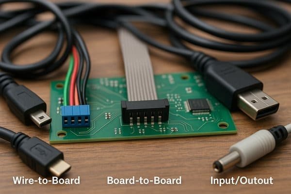
Connectors on a PCB bridge electrical pathways. Common types include wire-to-board (like JST, Molex), board-to-board (mezzanine, edge card), I/O (USB, HDMI, Ethernet), and RF connectors (SMA, U.FL). Each serves specific signal, power, or mechanical needs.

I've spent nearly 20 years in embedded systems, and if there's one thing I've learned, it's that connectors are far more than just plastic and metal bits. They are critical, often "invisible," components, especially when you're dealing with high-speed signals or power integrity. Thinking about them late in the design is a recipe for headaches. Let's break down what you need to know to keep your project moving smoothly.
What are the 3 types of cable connectors?
Staring at a pile of cables and wondering which connector does what? Using the wrong one means no connection or worse, damage. Let's clarify some common categories you'll encounter with PCBs.
For PCBs, cable connectors generally fall into: 1. Wire-to-Board (connecting discrete wires or multi-conductor cables to the PCB), 2. Board-to-Board (often via ribbon cables), and 3. Input/Output (I/O) connectors (linking the PCB to external devices or systems).
Exploring Cable Connector Categories
When we talk about cable connectors in the context of PCBs, we're usually looking at a few main scenarios. Each category serves a distinct purpose in linking your PCB to other parts of a system or the outside world. Understanding these helps in early-stage design planning. For instance, at Honeywell on the Tuxedo Keypad, we had all three types in one product: internal wire-to-board for sensors, ribbon cables for display modules, and USB/Ethernet for external I/O.
| Connector Category | Description | Common Examples | Key Considerations |
|---|---|---|---|
| Wire-to-Board | Connects discrete wires or multi-conductor cables to the PCB. | JST (PH, XH), Molex (PicoBlade, KK), Crimp Terminals | Current rating (e.g., 1A-5A), wire gauge (e.g., 22-28 AWG), locking mechanism. |
| Board-to-Board (via Cable) | Uses cables (e.g., ribbon, FFC/FPC) to link different PCBs. | Ribbon Cables with IDC connectors, FFC/FPC cables | Flexibility, signal integrity, pitch (e.g., 1.27mm, 0.5mm). |
| Input/Output (I/O) | Links the PCB to external devices or systems. | USB, Ethernet (RJ45), HDMI, D-Sub, Audio Jacks | Standardization (e.g., USB Type-C), EMI shielding, mating cycles (e.g., 1500+). |
How to choose PCB connectors?
So many connectors, so little time! If you choose poorly, you might face signal degradation, mechanical failure, or even production nightmares. The key is a systematic approach.
Choose PCB connectors by evaluating: 1. Electrical needs (current, voltage, signal speed, impedance). 2. Mechanical aspects (size, orientation, mating cycles, retention). 3. Environmental conditions (temperature, humidity, vibration). 4. Cost and availability.
Detailed Guide to Connector Selection
Selecting the right connector is a critical design step. As I mentioned, connectors are not just passive parts; they can be performance bottlenecks if chosen carelessly, especially for signal integrity (SI) and power integrity (PI). When I led hardware design for a next-gen infusion pump at Smiths Medical, connector selection for sensor integration was paramount – we needed high reliability and specific current ratings, often down to a few milliamps, but with very low contact resistance.
| Criteria | Considerations | Typical Values/Sources (Always verify with manufacturer datasheets) |
|---|---|---|
| Electrical | Current Rating (Amps per contact) | 0.5A to 50A+. Example: A JST PH (2.0mm pitch) is rated for 2A (AWG #24). Derating applies. Source: Datasheets (e.g., JST, Molex, TE Connectivity). |
| Voltage Rating (Volts) | 30V to 600V+. Depends on pitch and insulation. Example: Many small signal connectors are 50V-125V AC/DC. Source: Datasheets. | |
| Signal Integrity1 | Impedance matching (e.g., 50Ω for RF, 90Ω differential for USB 3.0, 100Ω for Ethernet). Insertion Loss (S21), Return Loss (S11). High-speed connectors (>1 Gbps) often have S-parameter models. Source: Samtec, Hirose datasheets. | |
| Contact Resistance2 (mΩ) | Initially 5mΩ to 30mΩ. Increases with mating cycles and age. Critical for power. Source: Datasheets. | |
| Mechanical | Pin Count & Pitch (mm) | Pins: 2 to 100+. Pitch: 0.3mm, 0.4mm, 0.5mm, 0.8mm, 1.0mm, 1.25mm, 1.27mm, 2.0mm, 2.54mm, etc. |
| Mating Cycles | Low: 10-50 (internal, one-time assembly). Medium: 100-500 (some I/O). High: 1,000-10,000+ (USB, ruggedized). Source: Datasheets. | |
| Orientation & Mounting | Vertical, Right-angle, Edge-mount. Through-hole (THT), Surface-mount (SMT). | |
| Retention Features | Friction lock, positive latch (e.g., Molex Mini-Fit Jr.), locking tabs, screws. | |
| Environmental | Operating Temperature3 (°C) | Commercial: 0°C to 70°C. Industrial: -40°C to 85°C. Automotive: -40°C to 125°C (AEC-Q100/200 for components). Source: Datasheets. |
| Sealing (IP Rating) | E.g., IP67 for dust/waterproof (IEC 60529). Important for harsh environments. | |
| Other | Cost & Availability | Consider volume pricing, lead times, and multiple sources. |
How do you connect two PCB boards together?
Need to link two circuit boards? A shaky connection can bring down your whole system. Reliable inter-board links are crucial for modular designs and complex electronics.
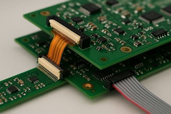
Connect two PCB boards using board-to-board connectors (like mezzanine/stacking or edge connectors), ribbon cables with IDC connectors mating to headers, or flexible printed circuits (FPCs) with specialized FPC connectors.
Methods for Inter-PCB Connection
Connecting multiple PCBs is common, and the choice of method impacts mechanical design, signal integrity, and cost. In aerospace projects, I've relied heavily on rugged board-to-board connectors for vibration resistance, while consumer products often use FPCs for their flexibility in tight spaces.
| Connection Method | Description | Typical Use Cases | Advantages | Disadvantages |
|---|---|---|---|---|
| Board-to-Board (B2B) Connectors4 | Direct PCB-to-PCB mating. | Stacking (Mezzanine), Right-angle (Edge Card), Backplanes | Compact, high-speed capable (e.g., >10 Gbps), secure. | Less flexible positioning, precise alignment needed. |
| Mezzanine/Stacking | Parallel stacking of PCBs. | Dense multi-board designs. | Various heights (e.g., 3mm-20mm+), fine pitch (e.g., 0.4mm, 0.5mm, 0.8mm). Samtec, Hirose are key suppliers. | Limited X-Y flexibility. |
| Edge Card | One PCB edge (gold fingers) inserts into a slot on another. | Expansion cards (PCIe, RAM), daughter cards. | Robust, standardized interfaces (e.g., PCIe CEM spec). | Fixed orientation (perpendicular/coplanar). |
| Ribbon Cables with IDC | Flat cables with Insulation Displacement Connectors mating to PCB headers. | Flexible inter-board connections, parallel data buses. | Flexible positioning, cost-effective for many signals (e.g., 2.54mm or 1.27mm pitch). | Not ideal for very high-speed/impedance control. |
| FPCs with FPC Connectors | Flexible circuits connecting via specialized ZIF/LIF connectors. | Tight spaces, connections requiring dynamic bending. | Very flexible, fine pitch (e.g., 0.3mm, 0.5mm), low profile. | FPC cost, delicate handling, connector durability. |
What are JST connectors used for?
You've seen those small white connectors, right? Not knowing what they are can stop your prototyping or repair dead in its tracks. Let's demystify them.
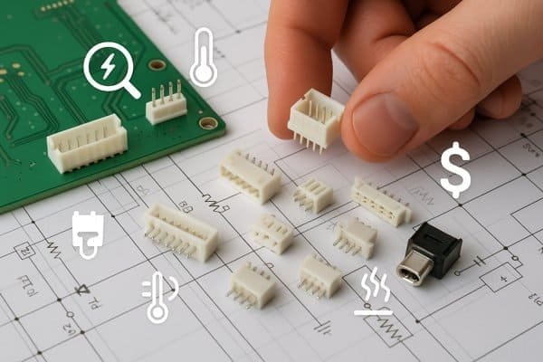
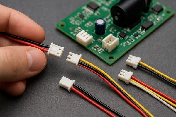
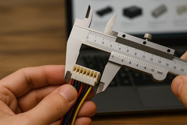
JST connectors, a brand name from JST Mfg. Co., refer to a wide variety of wire-to-board and wire-to-wire connectors. They are commonly used for low-power applications, batteries, sensors, motors, and internal wiring in consumer and industrial electronics.
Understanding Common JST Series
JST is a major manufacturer, and "JST connector" is a common term, but it covers many distinct series. It's crucial to identify the specific series by measuring pitch and checking features, as they are not interchangeable. For instance, the popular JST PH 2-pin is almost a standard for single-cell LiPo batteries in hobbyist electronics, but it's only rated for 2A.
| JST Series | Pitch | Typical Current Rating (per contact with specified AWG) | Common Applications | Key Features |
|---|---|---|---|---|
| PH | 2.0mm | 2A (AWG #24) | LiPo batteries (single cell), small electronics, RC models | Good friction lock, widely available. |
| XH | 2.5mm | 3A (AWG #22) | General purpose, fan power, sensor signals | Robust, often mistaken for 2.54mm pitch but incompatible. |
| SH | 1.0mm | 1A (AWG #28) | Very compact devices (displays, camera modules) | Tiny, space-saving, low profile. |
| GH | 1.25mm | 1A (AWG #26) | Similar to SH, often with a more secure positive lock. | Secure locking, compact. |
| SM | 2.5mm | 3A (AWG #22) | Wire-to-wire, LED lighting strips, hobby projects | Latching mechanism, typically wire-to-wire. |
(Note: Always verify with official JST datasheets for precise ratings, applicable wire gauges, and derating curves. Many "JST-style" connectors exist from other manufacturers; check their specs carefully.)
How to identify connector type?
Facing an unknown connector can be frustrating, especially when you need a mate or replacement. Panic sets in if you can't order the right part. But there's a method to this madness.
Identify a connector by: 1. Measuring pin pitch. 2. Counting pins/positions and rows. 3. Observing housing shape, color, and locking features. 4. Searching for manufacturer markings/part numbers. 5. Comparing to online catalogs using these parameters.
A Systematic Approach to Connector Identification
Identifying an unknown connector feels like detective work. Here’s a systematic approach I use, refined over years of debugging and reverse-engineering everything from elevator controls to photonic computing evaluation boards.
1. Measure Pin Pitch5
This is the distance from the center of one pin/contact to the center of the next. Use digital calipers for accuracy. Common pitches include: 0.3mm, 0.4mm, 0.5mm, 0.8mm, 1.0mm, 1.25mm, 1.27mm (0.05"), 2.0mm, 2.5mm, 2.54mm (0.1"), 3.96mm (0.156"). This is often the most critical dimension.
2. Count Pins and Rows
How many active positions are there? Is it a single row or dual row (or more)? For example, a "2x5 pin" connector has two rows of five pins each, for a total of 10 positions.
3. Observe Housing Characteristics
Note the housing's shape (rectangular, circular, D-shaped), color (though not always definitive), locking mechanisms (friction fit, latches, screws), and keying (slots/protrusions for orientation).
4. Look for Markings
Check for manufacturer logos (e.g., Molex flower, TE triangle, "JST") or any partial part numbers. These can be tiny, so a magnifying glass and good lighting are essential.
5. Determine Gender
Is it male (pins/blades) or female (sockets/receptacles)? For shrouded headers, the shroud is part of the male connector.
6. Consider Application Context
Where is it used? Power input (e.g., >5A may mean larger contacts), high-speed data (e.g., USB, HDMI have distinct shapes), RF signal (coaxial)? This can narrow down possibilities.
7. Utilize Online Resources
Distributor websites (Digi-Key, Mouser, Farnell) have powerful parametric search tools. Manufacturer websites (e.g., Samtec, Molex, TE, Hirose, JST) also have extensive catalogs. ConnectorBook.com is a great visual resource.
What is SMA in electronics?
You've probably seen "SMA" on Wi-Fi antennas or RF test equipment. If you're unsure what it is, you might overlook critical aspects of RF system design.
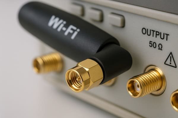
SMA (SubMiniature version A) connectors are coaxial RF connectors designed for high-frequency signals, typically from DC up to 18 GHz (some variants higher). They feature a 50-ohm characteristic impedance and a threaded coupling mechanism for secure connections.
SMA Connectors: Key Features and Considerations
SMA connectors are workhorses in the RF world. Their precise mechanical and electrical characteristics are vital. When I worked on the PACE evaluation board for a photonic chip at Lightelligence, ensuring clean SMA connections for high-speed test signals (multi-GHz) was absolutely critical; a poorly torqued or damaged connector could invalidate days of testing.
| Feature | Description / Typical Values | Importance / Notes |
|---|---|---|
| Frequency Range | Standard: DC to 18 GHz. Precision (e.g., stainless steel, tighter tolerances): Up to 26.5 GHz or higher. | Critical for RF performance; ensure connector rating exceeds operating frequency. Source: MIL-STD-348B. |
| Impedance | 50 Ohms characteristic. | Essential for matching cables and circuits to minimize reflections (VSWR) and maximize power transfer. |
| Coupling Mechanism | 1/4-36 UNS threaded barrel. | Provides secure, vibration-resistant connection. Proper torque is crucial: brass 0.34-0.56 Nm (3-5 in-lbs); stainless steel 0.79-1.13 Nm (7-10 in-lbs). Source: Manufacturer specs. |
| Construction | Outer conductor, dielectric (PTFE/Teflon), center pin (male) or socket (female). | Material quality (brass, stainless steel) affects performance, durability, and mating cycles (e.g., 500+). |
| Common Variation | RP-SMA (Reverse Polarity SMA): Center contact gender is swapped relative to the body. | Used in Wi-Fi equipment (per FCC Part 15) to prevent uncertified high-gain antenna connections. Male RP-SMA plug has a center socket. |
What are the different types of PCB spacers?
Mounting PCBs securely and with proper clearance is essential. Using the wrong spacer or standoff can lead to shorts, mechanical stress, or thermal issues.
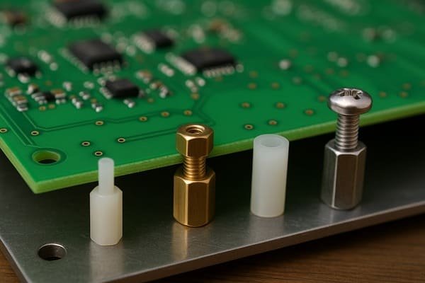
PCB spacers (or standoffs) create and maintain space between PCBs or between a PCB and a chassis. Common types include threaded (male-female, female-female), unthreaded (clearance), and snap-fit, made from materials like nylon, brass, or stainless steel.
PCB Spacers and Standoffs: Materials and Types
Spacers and standoffs are humble but crucial hardware. The choice impacts assembly, electrical safety, and mechanical stability. In industrial automation projects, I've often used hex brass standoffs for their strength and ability to be tightened securely, ensuring PCBs didn't vibrate loose.
Spacer/Standoff Materials
| Material | Key Properties | Typical Use Cases | Temperature Range (Typical, consult datasheet) |
|---|---|---|---|
| Nylon (Polyamide) | Lightweight, excellent electrical insulation, cost-effective. | General applications, preventing shorts, light loads. | -20°C to 85°C (standard), some up to 120°C. |
| Brass (Nickel-plated) | Good mechanical strength, conductive (can be for grounding). | Stronger mounts, potential grounding points, chassis. | -40°C to 150°C+. |
| Stainless Steel | High strength, excellent corrosion resistance, non-magnetic. | Harsh environments, heavy loads, medical, food grade. | -50°C to 200°C+. |
| Aluminum | Lightweight, good strength, good thermal conductivity. | Applications needing moderate strength and heat dissipation. | -40°C to 120°C+. |
Spacer/Standoff Types
| Type | Description | Common Threads/Features | Application Examples |
|---|---|---|---|
| Threaded Standoffs | Internal or external threads for screw mounting. | Metric: M2, M2.5, M3, M4. Imperial: #2-56, #4-40, #6-32. Lengths: 3mm - 50mm+. Hex or round body. | Stacking PCBs, mounting PCBs to panels. |
| Male-Female | Threaded stud on one end, threaded hole on the other. | Creating specific height stacks. | |
| Female-Female | Threaded holes on both ends. | Secure mounting with screws from both sides. | |
| Unthreaded Spacers | Smooth bore tubes; screw passes through. | Clearance for screw diameter. Often Nylon. | Simple spacing, electrical isolation. |
| Snap-Fit / Press-Fit | Snap or press into PCB/chassis holes. | Often plastic (Nylon); various locking designs (e.g., reverse-locking). For specific hole diameters (e.g., 3.2mm, 4mm). | Quick, tool-less assembly, light-duty retention. |
| Adhesive-Backed Spacers | Adhesive pad on one end. | Various heights (e.g., 4.8mm, 6.4mm). | Light-duty mounting where screws aren't feasible. |
How does an FPC connector work?
Connecting those paper-thin flexible circuits can be tricky. If you don't understand how FPC connectors work, you risk damaging the cable or getting an unreliable connection.
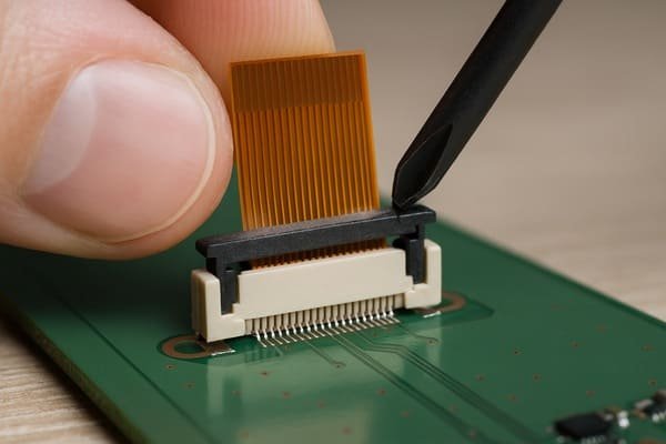
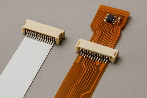
FPC (Flexible Printed Circuit) connectors secure FPCs by clamping them. Most use a ZIF (Zero Insertion Force) or LIF (Low Insertion Force) mechanism where an actuator presses the connector's contacts against the FPC's conductive traces, ensuring electrical continuity.
The Mechanics of FPC Connectors
FPC connectors are designed for the delicate nature of Flexible Printed Circuits (FPCs) or Flat Flexible Cables (FFCs). The clamping mechanism is key to a reliable connection without damaging the thin traces. I've seen many field failures in compact medical devices due to improperly seated FPCs – the actuator wasn't fully closed, or the cable was inserted skewed.
| Feature | ZIF (Zero Insertion Force6) | LIF (Low Insertion Force7) |
|---|---|---|
| Insertion Force | Virtually none; cable inserted when actuator is open. | Small amount of force required as contacts provide friction upon FPC insertion. |
| Actuator Type | Commonly "flip-lock" (hinged latch on top or front) or "slider" (part slides out/in). | Actuator may be less distinct or integrated; relies on contact spring force. Simpler structure. |
| FPC Wear | Minimal, as no force is applied during insertion/removal with actuator open. Better for high mating cycles (e.g., 10-30 cycles). | Can cause more wear on FPC traces over multiple mating cycles. Suited for fewer matings. |
| Common Use | Very common for fine-pitch FPCs (e.g., 0.3mm, 0.5mm, 1.0mm) and applications requiring durability. | Older designs or some robust applications where ZIF complexity is not needed. |
| Operation | 1. Open actuator. 2. Insert FPC fully and squarely. 3. Close actuator to clamp. | 1. Push FPC into connector until it seats against the back wall. |
(Critical: Always ensure FPC is fully inserted (often visual markers on FPC help), aligned, and actuator (if ZIF) is properly closed. Match FPC/FFC thickness (e.g., standard 0.3mm including stiffener) to connector specs. Contacts can be top, bottom, or dual.)
What is the difference between FFC and FPC connectors?
FFC, FPC... they sound alike and connect alike, causing confusion. Using the terms or connectors incorrectly can lead to miscommunication or incompatible parts. Let's clear this up.
FFC (Flat Flexible Cable) is a simple cable with straight parallel conductors. FPC (Flexible Printed Circuit) is a custom-etched flexible circuit board, potentially with components. Connectors are often "FFC/FPC" compatible if pitch and thickness match, but the cables/circuits themselves differ in complexity.
Distinguishing FFCs from FPCs
While the connectors used for FFCs and FPCs can often be the same (hence "FFC/FPC connector" designation by manufacturers like Molex or TE Connectivity), the flexible elements themselves are quite different. Understanding this helped me specify the right flexible interconnect for many projects, from simple display FFCs to complex FPCs with integrated sensors.
| Feature | FFC (Flat Flexible Cable) | FPC (Flexible Printed Circuit) |
|---|---|---|
| Construction | Multiple flat, straight copper conductors laminated between insulating film (e.g., polyester, PET). Conductors run parallel. | Custom-etched copper traces on a flexible substrate (e.g., polyimide, PI). Traces can be routed complexly. |
| Complexity | Simple point-to-point wiring. | Can have complex multi-layer trace routing, vias, controlled impedance, and support mounted SMT components. |
| Components | Generally cannot mount components directly. | Can have resistors, capacitors, ICs, LEDs, etc., mounted directly. Acts as a bendable PCB. |
| Design | Limited to straight, parallel connections. Available in standard conductor counts (e.g., 4 to 50). | High design freedom for custom shapes and circuit layouts. |
| End Prep | Insulation stripped, exposed conductors (contacts on one or both sides). Often has a stiffener (e.g., blue polyester, 0.1mm thick) for connector insertion. | End designed for specific connector; can be complex if components are nearby. Stiffeners (e.g., polyimide) also used. |
| Cost | Generally less expensive for simple connections due to simpler manufacturing. | More expensive due to complex manufacturing (etching, lamination, component assembly if any). |
(Note: Many connectors (e.g., ZIF, LIF) are designated "FFC/FPC compatible" if critical dimensions like pitch (e.g., 0.5mm, 1.0mm), conductor width/spacing, and overall thickness at the insertion point (e.g., 0.3mm ±0.05mm including stiffener) match the connector's specifications.)
Conclusion
Choosing PCB connectors correctly is vital. It involves balancing electrical needs, mechanical constraints, and the intended application to ensure reliable system performance. Remember, they're active parts of your design.
-
Understanding Signal Integrity is crucial for ensuring reliable performance in electronic designs, especially in high-speed applications. ↩
-
Exploring Contact Resistance helps in selecting connectors that maintain low resistance for better power efficiency and reliability. ↩
-
Knowing the Operating Temperature range is vital for ensuring connectors perform reliably in various environmental conditions. ↩
-
Explore this link to understand how B2B connectors enhance PCB design with high-speed capabilities and secure connections. ↩
-
Understanding pin pitch is crucial for accurate connector identification and ensuring compatibility in electronic designs. ↩
-
Learn about ZIF technology to see how it enhances the reliability and ease of use in electronic connections. ↩
-
Discover the benefits of LIF technology and its applications in various electronic devices. ↩


