 Skip to content
Is your high-speed interface failing eye-diagram tests, or is your power supply control loop showing strange oscillations? Before you blame the silicon, the answer might lie in the second-order effects of the most common component on your board: the capacitor.
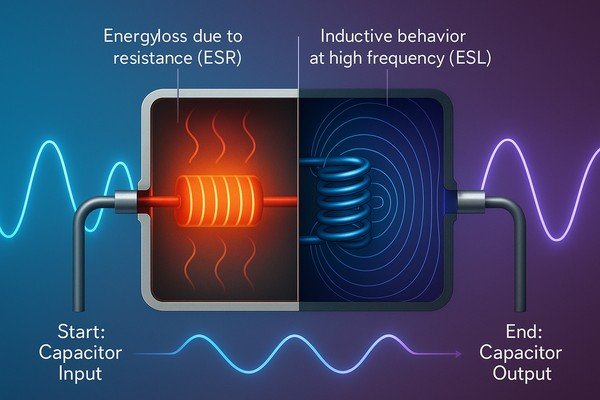
ESR (Equivalent Series Resistance) is the real part of a capacitor’s impedance and represents energy lost as heat due to internal resistance. ESL (Equivalent Series Inductance) is the parasitic inductance resulting from the capacitor’s leads and internal structure. Together, ESR and ESL affect a capacitor's behavior at high frequencies, influencing resonance, energy losses, and circuit stability.
As a hardware engineer, I've learned that mastering the fundamentals isn't enough. True product reliability comes from understanding the subtle, non-ideal behaviors of passive components. Let's move beyond the basics and explore the deep engineering implications of \(ESR\) and \(ESL\).
What is the ideal capacitor model vs. a real capacitor model?
Are you still using the basic \(C+ESR+ESL\) model for your simulations? For demanding applications, this simplification can be misleading and hide potential failures in your design.
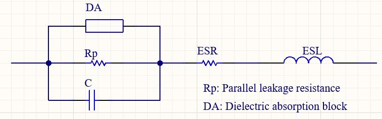
An ideal capacitor has pure capacitance. A real capacitor's model must also include \(ESR\) and \(ESL\). For expert-level analysis, we must also consider parallel leakage resistance (\(R_{p}\)) and dielectric absorption (\(DA\)), which can significantly impact precision analog circuits.
Deconstructing the Real Capacitor Model: More Than Just Capacitance
Choosing the right capacitor goes beyond the primary value; it's about understanding the trade-offs of the dielectric material. The table below compares common dielectric types.
| Dielectric Type | Key Characteristics | Best For | Avoid For |
|---|---|---|---|
| C0G/NP0 (Class I Ceramic) | Ultra-stable, low loss, no DC bias effect, low DA. | RF filters, tuning, precision analog (integrators). | High-density bulk decoupling (low \(C\)/volume). |
| X7R/X5R (Class II Ceramic) | High \(C\)/volume, moderate stability. Capacitance drops with DC bias and temperature. | General purpose decoupling, power supplies. | Precision timing or filtering circuits. |
| Aluminum Electrolytic | Highest \(C\)/volume, high \(ESR\)/\(ESL\), limited life, polarity sensitive. | Bulk energy storage, low-frequency filtering. | High-frequency decoupling, high-temp applications. |
| Polymer/Tantalum | Lower \(ESR\) than electrolytics, stable, high \(C\)/volume. | SMPS output filtering, high-performance decoupling. | Tantalums require significant voltage de-rating. |
A classic example I encountered was in a medical-grade integrator circuit. The output wouldn't settle at zero, showing a slow drift. The cause was dielectric absorption in the X7R integration capacitor. Switching to a C0G/NP0 type, despite its lower capacitance density, completely eliminated the drift.
What is the self-resonant frequency (SRF) of a capacitor?
Are your RF filters exhibiting poor stop-band attenuation? You might be operating above the capacitor's series \(SRF\), but have you considered the impact of parallel resonance?
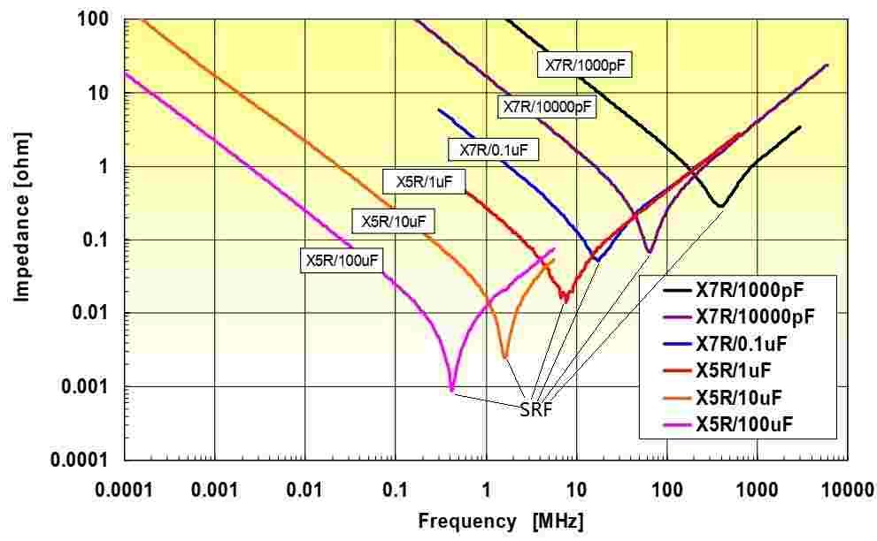
The self-resonant frequency (SRF) of a capacitor is the frequency at which the capacitor's capacitive reactance and inductive reactance cancel each other out. At this point, the capacitor exhibits purely resistive behavior, and its impedance reaches a minimum value, equal to its equivalent series resistance (ESR).
How Capacitor Size and Value Determine SRF
The formula \(SRF_{series} = \frac{1}{2\pi\sqrt{ESL \cdot C}}\) shows that \(SRF\) is inversely proportional to both capacitance and inductance. For a given capacitance, minimizing \(ESL\) is the key to achieving a higher \(SRF\). This makes package selection a critical design decision.
Here’s a practical comparison for a 100 nF (0.1 µF) capacitor:
| Package Type | Dimensions (mm) | Typical \(ESL\) (pH) | Calculated \(SRF\) (approx.) |
|---|---|---|---|
| Standard 0805 | 2.0 x 1.25 | 700 | 19.0 \(\text{MHz}\) |
| Standard 0603 | 1.6 x 0.8 | 500 | 22.5 \(\text{MHz}\) |
| Standard 0402 | 1.0 x 0.5 | 350 | 26.9 \(\text{MHz}\) |
| Reverse Geometry 0306 | 0.8 x 1.6 | 250 | 31.8 \(\text{MHz}\) |
| Inter-Digitated (IDC) 0508 | 2.0 x 1.25 | \(<100\) | \(>50 \text{ MHz}\) |
For truly high-frequency work (\(>1 \text{ GHz}\)), even these models are insufficient. Accurate simulation requires using the manufacturer's S-parameter1 (Touchstone) files, which capture the complex impedance behavior over a wide frequency range.
What are the negative effects of ESR in a circuit?
You know high \(ESR\) causes heat and ripple, but have you considered its effect on the noise floor of your precision analog circuits or the stability of your LDOs?
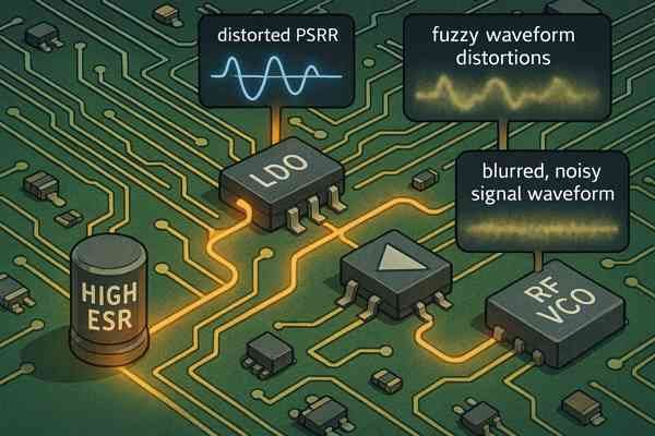
Beyond \(I^{2}R\) heating and simple voltage ripple, high \(ESR\) can degrade the Power Supply Rejection Ratio (\(PSRR\)) of sensitive components like LDOs and op-amps, and increase the phase noise in RF circuits like VCOs.
Beyond Heat: How ESR Degrades Precision Circuits and Reliability
The consequences of high \(ESR\) go far beyond simple inefficiency. They can introduce subtle, hard-to-diagnose noise problems and lead to premature product failure.
| High \(ESR\) Effect | Affected Circuit/Parameter | Physical Consequence |
|---|---|---|
| Power Dissipation (\(I^{2}R\) Loss) | Capacitor's core temperature. | Reduced operational lifespan, potential damage to nearby parts. |
| Voltage Drop (Ripple) | Power supply rails (\(V_{cc}\)). | Unstable voltage, can cause digital logic errors or resets. |
| Reduced Filtering | LDOs, Op-Amps, ADCs. | Degraded \(PSRR\), allowing more noise into sensitive circuits. |
| Increased Noise | VCOs, RF Synthesizers. | Increased phase noise, poor signal quality. |
The impact on precision circuits is critical. The Power Supply Rejection Ratio2 (\(PSRR\)) of a Low-Dropout Regulator (LDO) is highly dependent on the quality of its output capacitor. At high frequencies, the LDO's internal amplifier has less gain, and rejection capability relies on the output capacitor to shunt noise to ground. High \(ESR\) creates a higher impedance path, allowing more noise onto the regulated output.
Why is low ESR important for decoupling capacitors?
Meeting a target impedance is the goal of \(PDN\) design, but have you accounted for the mounting inductance of the capacitor, which can often be a bigger problem than its internal \(ESL\)?
Low \(ESR\) is fundamental for decoupling, as it sets the minimum possible impedance at the capacitor's \(SRF\). However, achieving low \(PDN\) impedance in practice requires co-designing the capacitor selection with the PCB layout to minimize mounting inductance.
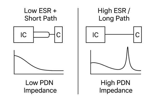
The Hidden Challenge of PDN Design: Mounting Inductance
The impedance seen by an IC is the sum of the capacitor's impedance and the impedance of the path connecting it. Minimizing this path, or mounting, inductance is critical.
\(Z_{total} = Z_{mounting} + Z_{capacitor} = (R_{mount} + j\omega L_{mount}) + (ESR + j\omega ESL - \frac{j}{\omega C})\)
The mounting inductance (\(L_{mount}\)) is the inductance of the PCB pads, traces, and vias. A typical via can add 0.4-0.8 \(\text{nH}\) of inductance. A capacitor's internal \(ESL\) might be 350 \(\text{pH}\) (0.35 \(\text{nH}\)), but if it's connected with long traces and two vias, the mounting inductance could easily add another 1-2 \(\text{nH}\), completely dominating the high-frequency response.
| Layout Technique | Relative Mounting Inductance | Best Use Case |
|---|---|---|
| Long Trace Fan-out | High | Avoid for high-speed decoupling. |
| Short, Wide Trace Fan-out | Medium | Good general practice. |
| Multiple Vias per Pad | Low | High-current and high-frequency applications. |
| Via-in-Pad (VIP)3 | Very Low | High-density designs (e.g., BGAs) where space is critical. |
I once worked on an FPGA board that was failing timing closure. The simulations were fine, but the power rail noise was exceeding the spec. The root cause wasn't the capacitors, but the layout. The decoupling caps were placed on the opposite side of the board and connected with long vias. A board respin with the capacitors placed on the same side, directly next to the BGA with optimized via connections, solved the problem completely.
How does ESR affect the performance of a switching power supply?
You know \(ESR\) creates ripple and affects the ESR-zero, but how does this interact with different control topologies, and what are the implications of the modern trend towards all-ceramic output capacitors?
\(ESR\)'s impact on a switching power supply extends beyond ripple and efficiency. It is a critical parameter for control loop compensation, and its role differs between voltage-mode and current-mode control. The low \(ESR\) of ceramic capacitors presents both an opportunity and a stability challenge.
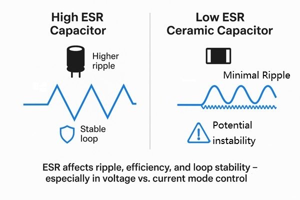
ESR's Critical Role in SMPS Control Loop Stability
The \(ESR\) of the output capacitor is a fundamental component in the power supply's transfer function, directly impacting how it responds to changes. The \(ESR\) zero, \(f_{zero,ESR} = \frac{1}{2\pi \cdot ESR \cdot C_{out}}\), provides a phase boost that can be crucial for stabilizing the control loop.
| Output Capacitor Type | Typical \(ESR\) | Impact on \(ESR\) Zero | Stability Consideration |
|---|---|---|---|
| Aluminum Electrolytic | High (50-500 \(\text{m}\Omega\)) | Places zero at a low, useful frequency. | Often necessary for stability in older voltage-mode designs. |
| Solid Polymer | Medium (10-50 \(\text{m}\Omega\)) | Places zero at a mid-frequency. | A good balance of low ripple and manageable stability. |
| MLCC (Ceramic) | Very Low (\(< 10 \text{ m}\Omega\)) | Pushes zero to a very high frequency. | Loses the stabilizing phase boost; can cause oscillation. |
The modern trend of using Multi-Layer Ceramic Capacitors (MLCCs) for the output stage offers huge benefits in reducing ripple but creates a new stability problem. The \(ESR\) is so low that the \(ESR\) zero is pushed to a very high frequency, meaning its stabilizing phase boost is lost. This can cause a well-designed voltage-mode converter to oscillate.
What are the symptoms of a bad capacitor with high ESR on a circuit board?
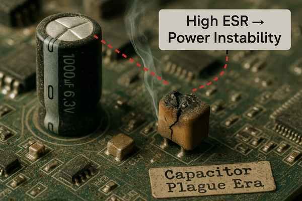
Bulging caps are an easy find, but can you identify the more subtle signs of a failing tantalum capacitor or recognize the legacy of the "capacitor plague"?
While bulging electrolytic caps are a classic sign, failing tantalum capacitors often fail short, causing catastrophic damage. Furthermore, understanding historical manufacturing defects, like the "capacitor plague," can provide crucial context when troubleshooting older equipment.
Identifying Failure Modes: From Bulging Electrolytics to Failing Tantalums
Not all capacitor failures are visually obvious. Knowing the distinct failure signatures of different capacitor types is a key diagnostic skill.
| Capacitor Type | Primary Failure Mode | Common Symptoms & Risks |
|---|---|---|
| Wet Aluminum Electrolytic | Fails "open" (High \(ESR\)). | Bulging top, leaking fluid, system instability, whining noise. |
| Solid Tantalum | Fails "short". | Catastrophic short circuit, glowing hot, potential fire/smoke. |
| MLCC (Ceramic) | Fails short (due to cracks). | No visual sign, shorts the power rail, can cause widespread damage. |
| "Plague" Era Electrolytic | Premature high \(ESR\). | Intermittent faults on equipment from \(\approx\) 2002-2007, even without visual signs. |
A fascinating piece of engineering history is the "Capacitor Plague4" of the early 2000s. A faulty electrolyte formula led to the mass production of capacitors that would fail prematurely. When I work on equipment from that era, I'm immediately suspicious of the electrolytic capacitors.
How is a capacitor's ESR measured?
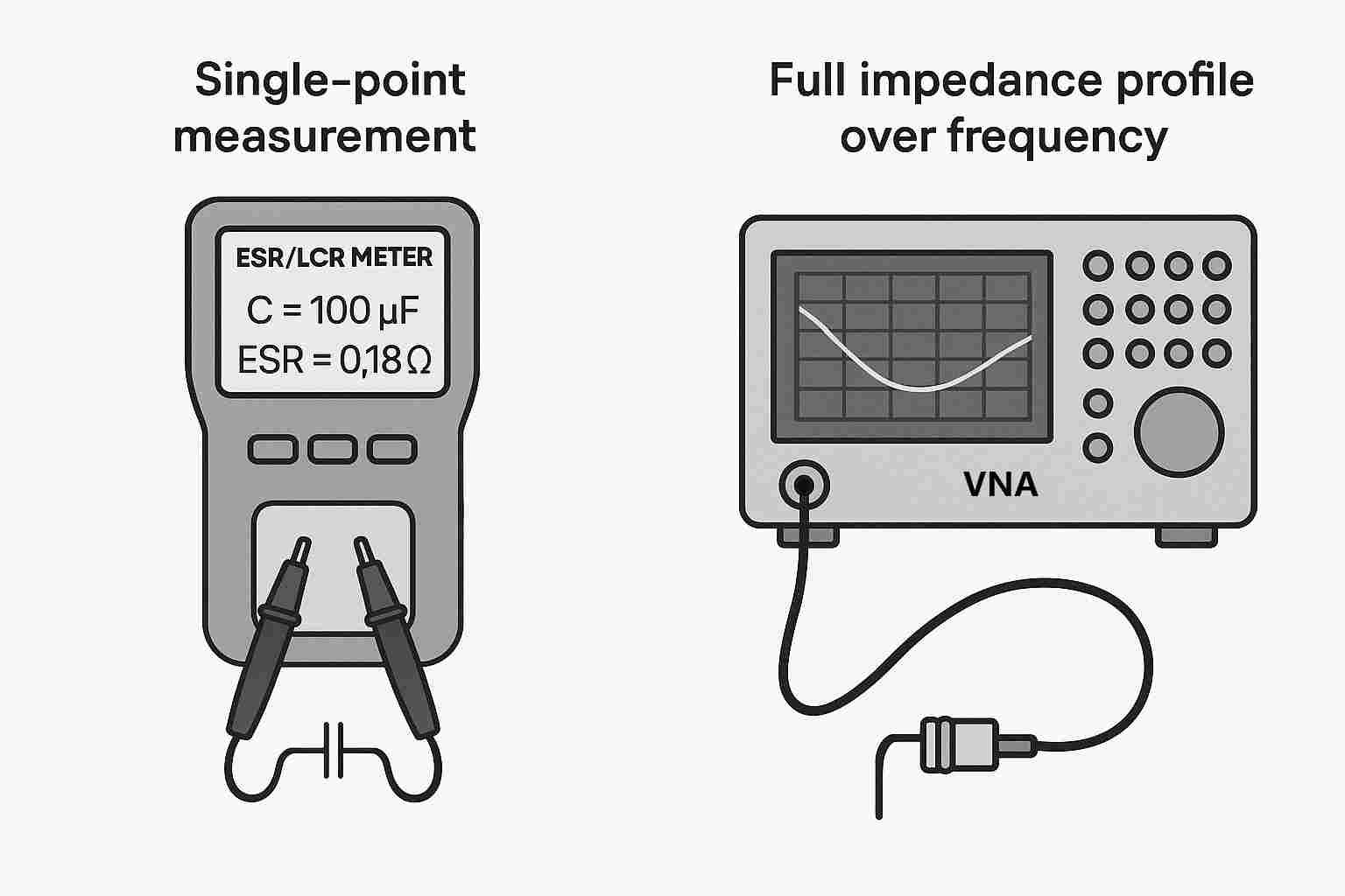
An \(ESR\) meter is great for troubleshooting, but for high-frequency design validation, how do you get a true, broadband impedance profile of your component?
While \(ESR\) and LCR meters are essential bench tools, a Vector Network Analyzer (VNA) is the gold standard for characterizing component impedance. It measures the S-parameters (\(S_{11}\)) of the capacitor, from which a complete impedance profile can be calculated over a multi-GHz range.
A Hierarchy of Measurement Tools: From ESR Meters5 to VNAs
The right tool for measuring \(ESR\) depends on whether you are troubleshooting a fault or validating a new design.
| Tool | Application & Limitations |
|---|---|
| \(ESR\) Meter | Troubleshooting & Repair. Ideal for quickly checking electrolytic caps in-circuit. Its primary limitation is that it measures at a single, fixed frequency (usually 100 \(\text{kHz}\)) and is not highly accurate. |
| LCR Meter | Design & Validation. Provides accurate \(C\), \(L\), and \(R\) (\(ESR\)) measurements at selectable frequencies. It's the standard tool for verifying a component against its datasheet specs. Requires desoldering for accuracy. |
| Vector Network Analyzer (VNA)6 | High-Frequency & \(PDN\) Characterization. This is the expert's tool. A VNA measures the reflection coefficient (\(S_{11}\)) of the device under test (DUT) over a broad frequency sweep. From \(S_{11}\), you can calculate the complex impedance (\(Z = Z_{0} \cdot \frac{1+S_{11}}{1-S_{11}}\)) at every frequency point. |
When using an \(ESR\) meter in-circuit, a powerful diagnostic technique is comparative measurement. If you have a board with multiple identical channels, measure the \(ESR\) of the same capacitor in each channel. A significant deviation in one channel compared to the others is a strong indicator of a fault.
Conclusion
Mastering capacitor behavior means moving beyond ideal models. By understanding the deep implications of \(ESR\), \(ESL\), dielectric choice, and mounting inductance, you can transform your designs from merely functional to truly robust and reliable.
For more discussions about ESR/ESL, please read my article: What are the Negative Effects of ESL in a Circuit?
-
Exploring S-parameters will enhance your knowledge of complex impedance in capacitor design. ↩
-
Exploring PSRR will enhance your knowledge on maintaining stable voltage and reducing noise in sensitive circuits. ↩
-
Learn how Via-in-Pad (VIP) technology reduces mounting inductance, enabling high-density, high-performance PCB layouts for advanced electronics. ↩
-
Understanding the Capacitor Plague can help you avoid similar issues in vintage electronics and improve your repair skills. ↩
-
Explore this link to understand how ESR Meters work and their importance in diagnosing electronic faults. ↩
-
Learn about VNAs to grasp their role in advanced electronic testing and characterization. ↩


