 Skip to content
Struggling with high-frequency noise, transient response failures, or unexplained system instability? You've followed the app notes, but your design is still marginal. The root cause often lies beyond basic component selection and deep within the parasitic effects that govern high-performance circuits.
The primary negative effect of Equivalent Series Inductance (\(ESL\)) is that it transforms a capacitor into an inductor above its self-resonant frequency, causing impedance to rise and fundamentally undermining its role in filtering and decoupling. This effect is a primary limiter in all modern high-speed digital and power systems.
In my nearly 20 years as a hardware engineer, I've learned that the difference between a functional prototype and a reliable, mass-producible product is often an expert-level understanding of these second-order effects. This guide goes beyond the basics to explore the deep impact of parasitics and how to master them.
How Does ESL Affect Capacitor Performance at High Frequencies?
Your capacitor should be a frequency-dependent short circuit, but it's not. This discrepancy between the ideal and the real is the source of countless high-speed design failures.
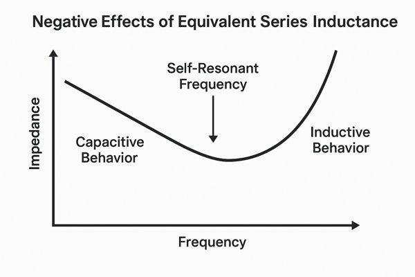
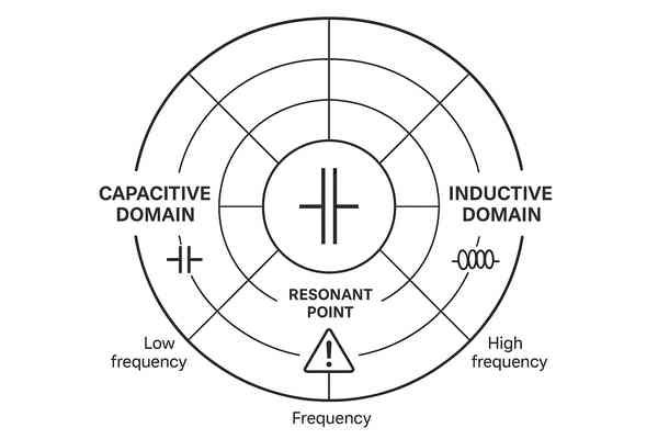
At high frequencies, a capacitor's \(ESL\) generates inductive reactance (\(X_{L} = 2\pi f L\)) that eventually overtakes its capacitive reactance. This inflection point, the self-resonant frequency (\(SRF\)), marks the boundary where the capacitor ceases to function as intended and becomes part of the problem.
From Capacitor to Inductor: The Impact of Self-Resonant Frequency (SRF)1
A real-world capacitor is an \(RLC\) circuit. Understanding its behavior across the frequency spectrum is non-negotiable.
-
Physical Origins of \(ESL\): This inductance isn't magical; it comes from the physical construction of the capacitor. It's the sum of the inductance from the internal metal plates, the external terminals (or leads), and the way they are connected. A longer current path inside and outside the component results in higher \(ESL\). This is why smaller surface-mount packages (like 0402 or 0201) inherently have lower \(ESL\) than larger packages or leaded components.
-
Capacitor Behavior vs. Frequency:
- Below \(SRF\): The device is capacitive. Impedance is dominated by capacitive reactance (\(X_{C} = \frac{1}{2\pi f C}\)) and drops at a rate of \(-20 \text{ dB/decade}\) on a log-log plot.
- At \(SRF\): This is the point of minimum impedance, where \(|X_{C}| = |X_{L}|\). Impedance equals the \(ESR\). The formula is: \(SRF = \frac{1}{2\pi\sqrt{ESL \times C}}\).
- Above \(SRF\): The device is inductive. Impedance is dominated by inductive reactance (\(X_{L} = 2\pi f \times ESL\)) and rises at a rate of \(+20 \text{ dB/decade}\).
I once worked on a communications project where EMI compliance was failing at exactly \(450 \text{ MHz}\). After weeks of shielding and filtering, we discovered the problem was a \(10\text{nF}\) decoupling capacitor. Its \(SRF\) was around \(150 \text{ MHz}\), meaning at \(450 \text{ MHz}\), it was acting as a nice little inductor, resonating with other board structures and creating a perfect unintentional antenna. Swapping it for a \(1\text{nF}\) capacitor in a smaller package, which had an \(SRF\) over \(600 \text{ MHz}\), solved the problem instantly.
How Does ESL Affect High-Frequency Decoupling?
You've populated your board with dozens of decoupling capacitors, yet your FPGA is still experiencing bit errors. The reason is that the capacitors' effectiveness is being strangled by inductance.
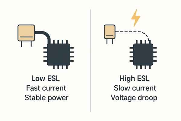
\(ESL\), combined with the layout inductance of the PCB, creates a high-impedance path that chokes off the instantaneous current demanded by fast-switching ICs. This results in power rail collapse (voltage droop) and ground bounce, which are direct causes of data corruption and system crashes.
Why Total Loop Inductance Matters More Than Component ESL
The IC doesn't care about the capacitor's datasheet \(ESL\); it cares about the total loop inductance of the path the current must travel from the capacitor to the silicon die and back. This includes:
\(L_{total} = L_{cap} + L_{trace} + L_{pad} + L_{via} + L_{plane\_spreading} + L_{BGA\_ball} + L_{package} + L_{die}\)Minimizing this entire chain is the true art of high-speed decoupling.
Advanced Mounting Techniques
The mounting inductance can easily be 2-3x the capacitor's own internal \(ESL\). This table provides typical inductance values for vias in a standard 1.6mm PCB, which can vary based on specific geometry.
| Via Mounting Style | Typical Added Inductance (per via) | Best For |
|---|---|---|
| Standard Vias | \(\approx 400 - 600 \text{ pH}\) | General purpose, non-critical signals |
| Via-in-Pad (VIP) | \(\approx 100 - 200 \text{ pH}\) | High-speed decoupling, BGA breakouts |
| Multiple Vias | Inductance reduces in parallel | Critical power/ground connections |
The Pitfall of Parallel Resonance
When you place capacitors of different values in parallel (e.g., \(10\text{µF}\), \(100\text{nF}\), \(1\text{nF}\)), you create multiple \(RLC\) circuits. This combination leads to anti-resonant peaks2—sharp spikes in impedance—at frequencies between the individual \(SRF\)s of the capacitors. If an anti-resonant peak aligns with a critical frequency (like a clock harmonic), it can dramatically amplify noise. This is why modern PDN design relies on simulation to carefully select capacitor values and quantities to smooth out the impedance profile and dampen these peaks.
In What Types of Circuits are ESR and ESL Most Important?
Parasitics aren't just an RF problem; they are a fundamental challenge in any circuit that switches, moves, or processes data quickly.
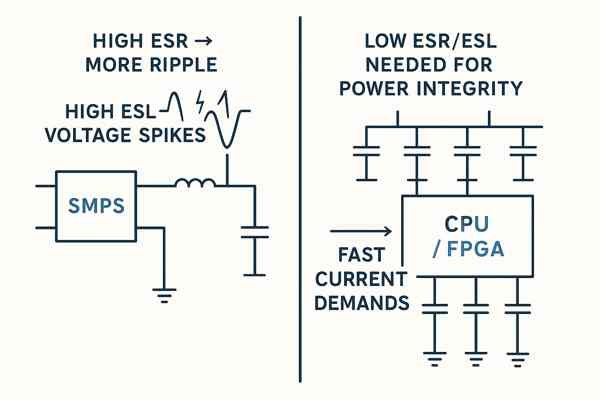
\(ESR\) and \(ESL\) are critically important in Switch-Mode Power Supplies (SMPS), where they dictate efficiency and stability, and in high-speed digital systems (FPGAs, CPUs, ASICs), where they are the primary roadblock to achieving power integrity.
Impact of Parasitics in Power, Digital, and RF Systems
Switch-Mode Power Supplies (SMPS)
In an SMPS, \(ESR\) directly translates to wasted heat and inefficiency. For an output capacitor with \(2\text{A}\) of ripple current, an \(ESR\) of \(50 \text{ m}\Omega\) creates \(P_{loss} = I^{2}R = (2\text{A})^{2} \times 0.050\Omega = 200\text{mW}\) of wasted power. This heat reduces the capacitor's lifespan and the system's overall efficiency. Low \(ESL\) is also vital for the output cap to respond instantly to large load transients.
High-Speed Digital Circuits
Here, the game is about achieving a frequency-dependent target impedance. It's not just one number. An FPGA might need an impedance below \(10 \text{ m}\Omega\) up to \(20 \text{ MHz}\) to support core logic switching, but then require an impedance below \(3 \text{ m}\Omega\) from \(100 \text{ MHz}\) to \(500 \text{ MHz}\) to support its high-speed SerDes transceivers. Meeting these complex impedance profiles is impossible without a deep understanding of \(ESL\) and requires sophisticated PDN simulation.
RF Circuits
In RF circuits, parasitics become part of the design. The \(ESL\) of a capacitor can be intentionally used to create a resonant or filter circuit. \(ESR\) is a direct measure of loss; in a high-\(Q\) filter or oscillator, a low \(ESR\) is mandatory for achieving the required performance.
Which Types of Capacitors Have Low ESR and ESL?
Your component library is filled with options. Choosing the right technology is the first step toward a successful design.
Multi-Layer Ceramic Capacitors (MLCCs) offer the best combination of low \(ESR\) and low \(ESL\), especially in modern small packages. For high-capacitance bulk decoupling, polymer-based technologies (tantalum and aluminum) are superior to traditional electrolytics.
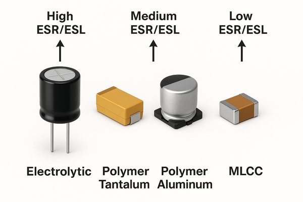
A Practical Comparison of Low-ESR/ESL Capacitor Technologies
| Capacitor Technology | Typical \(ESL\) | Typical \(ESR\) | Key Strengths | Key Weaknesses |
|---|---|---|---|---|
| Std. MLCC | \(0.3 - 1.5 \text{ nH}\) | \(1 - 10 \text{ m}\Omega\) | Excellent all-around, small size | Capacitance drops with DC bias |
| Polymer Tantalum | \(1 - 3 \text{ nH}\) | \(7 - 100 \text{ m}\Omega\) | High capacitance, very low ESR, stable | Lower voltage ratings, more expensive |
| Reverse Geometry MLCC | \(0.15 - 0.4 \text{ nH}\) | \(1 - 5 \text{ m}\Omega\) | Extremely low ESL for its size | Higher cost, less common |
| Inter-Digitated (IDC) | \(< 0.1 \text{ nH}\) | \(1 - 5 \text{ m}\Omega\) | Lowest possible ESL, superior HF performance | Expensive, specialized use |
| Aluminum Electrolytic | \(> 10 \text{ nH}\) | \(> 100 \text{ m}\Omega\) | High capacitance per dollar, high voltage | Very high parasitics, short lifespan |
The Hidden Killers: DC Bias and Temperature Derating
This is an expert-level "gotcha" that catches many engineers. The stated capacitance of Class 2 MLCCs (like those with \(X7R\) or \(X5R\) dielectrics) is not what you get in your circuit.
- DC Bias: As you apply a DC voltage, the effective capacitance drops—dramatically. A \(10\text{µF}\), \(16\text{V}\) \(X5R\) capacitor might only provide \(3\text{µF}\) of capacitance when operated at a \(9\text{V}\) bias.
- Temperature: Capacitance also varies with temperature. An \(X7R\) dielectric is only guaranteed to be within \(\pm 15\%\) of its nominal value from \(-55^{\circ}\text{C}\) to \(+125^{\circ}\text{C}\).
You must consult the manufacturer's datasheets for these derating curves and select a capacitor that provides the required capacitance at your operating voltage and temperature. Failing to do so is a common reason why decoupling schemes that look good on paper fail in reality.
How to Select a Capacitor for a Switch-Mode Power Supply (SMPS)?
An SMPS is a finely tuned system. The wrong passive components will disrupt its balance, leading to noise, instability, and premature failure.
For an SMPS, capacitors must be selected based on a multi-variable analysis of capacitance, voltage rating, ripple current capability, \(ESR\), and \(ESL\), all considered across the full operating temperature range.
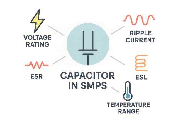
Selecting SMPS Components: A Focus on Capacitor and Inductor Parasitics
This table highlights the differing priorities for selecting input and output capacitors in a typical buck converter.
| Parameter | Input Capacitor (\(C_{in}\)) Priority | Output Capacitor (\(C_{out}\)) Priority | Justification |
|---|---|---|---|
| Ripple Current Rating | CRITICAL | Medium | \(C_{in}\) handles high, pulsed input current, causing significant self-heating. |
| \(ESR\) | High | CRITICAL | \(C_{out}\)'s \(ESR\) directly determines the magnitude of the output voltage ripple. |
| \(ESL\) | Medium | High | Low \(ESL\) in \(C_{out}\) is vital for a fast response to sudden load changes (transients). |
| Capacitance | High | High | Both need sufficient capacitance for energy storage and voltage stability. |
Don't Forget the Inductor's Parasitics
A capacitor doesn't work in a vacuum. In an SMPS, it works with an inductor, which has its own critical parasitics:
- DC Resistance (\(DCR\)): This is the simple wire resistance of the inductor's winding. Like \(ESR\) in a capacitor, it's a direct source of \(I^{2}R\) power loss, reducing efficiency.
- \(SRF\): Just like a capacitor, an inductor has a self-resonant frequency, caused by parasitic capacitance between its windings. Above its \(SRF\), an inductor starts to behave like a capacitor. This can cause high-frequency ringing and instability in an SMPS if not properly accounted for.
Optimizing an SMPS requires co-designing the capacitor and inductor choices to manage the parasitics of both.
How is the Appropriate Capacitor Selected for a Decoupling Application?
Effective decoupling is not about populating a board with capacitors; it's about engineering a low-impedance power delivery network from the voltage regulator to the silicon die.
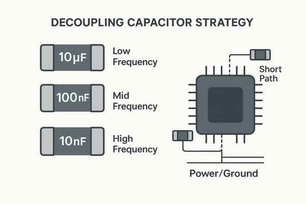
Decoupling capacitors are selected and placed to meet a frequency-dependent target impedance profile. This requires a multi-stage strategy using different capacitor technologies and advanced PCB layout techniques.
A Modern Decoupling Strategy: From PCB Stackup to Component Placement
Step 1: Define the Target Impedance (\(Z_{target}\)). Start with the simple formula, but for complex ICs, obtain the frequency-dependent impedance mask from the IC vendor.
Step 2: Engineer the PCB Stackup. Your first and best decoupling capacitor is the PCB itself.
- Plane Capacitance: By placing a power plane and a ground plane very close together (e.g., \(2-4 \text{ mils}\) or \(50-100 \text{ µm}\)), you create a high-quality, extremely low-inductance distributed capacitor. This is the most effective way to provide decoupling at frequencies \(> 500 \text{ MHz}\).
- Embedded Capacitance Materials (ECM): For ultimate performance, you can use special thin-film dielectrics in your PCB stackup that have a much higher dielectric constant than standard \(\text{FR-4}\). This can dramatically increase the plane capacitance, but it comes at a significant cost.
Step 3: Select and Simulate the Capacitor Array. Choose a mix of bulk, mid-range, and high-frequency capacitors. Use a PDN analysis tool (e.g., Keysight ADS PIPro, Cadence Sigrity) to simulate the entire system—including the PCB stackup, plane shapes, vias, and capacitor models—to ensure you meet your target impedance across the entire frequency range.
Step 4: Perfect the Layout. The simulation is only valid if the physical layout is perfect. Minimize loop inductance on every single decoupling path.
How Can the ESR and ESL Values Be Found for a Specific Capacitor?
"Garbage in, garbage out" is the law of simulation. Using inaccurate models for your components will render your analysis useless.
Authoritative \(ESR\) and \(ESL\) data is found in manufacturer-provided \(S\)-parameter models. Datasheet graphs are a good starting point, but for high-frequency simulation, nothing less than a high-quality, measurement-based model will suffice.
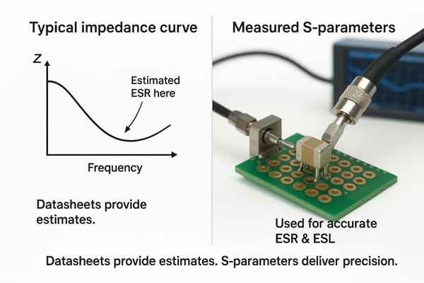
Acquiring Accurate Parasitic Data: Datasheets, Models, and Measurement
S-Parameter3 Models
This is the gold standard. A 2-port series-through \(S\)-parameter model (\(.s2p\)) captures the full frequency-dependent behavior of the capacitor. When using these, ensure your simulation tool correctly de-embeds the port structures to avoid double-counting fixture inductance.
The Limit of PCB Decoupling: The Silicon Itself
Even with the best capacitors and layout, there is a frequency limit to what PCB-level decoupling can achieve due to the unavoidable inductance of the IC package. Above \(\text{a few hundred MHz}\), the IC must rely on on-chip decoupling. This consists of millions of tiny MOS capacitors built directly onto the silicon die, right next to the switching logic. As a board-level designer, your job is to provide a low-impedance power source up to the frequency where the on-chip decoupling can take over.
Conclusion
Mastering parasitic effects like \(ESL\) is no longer an optional skill; it is the core competency of a high-performance hardware engineer. It requires moving beyond simple rules of thumb and embracing a holistic approach that integrates component physics, advanced layout techniques, and rigorous simulation.
-
Understanding SRF is crucial for optimizing capacitor performance in circuits, ensuring effective design and functionality. ↩
-
Exploring anti-resonant peaks will help you grasp their impact on impedance and noise, essential for effective PDN design. ↩
-
Learn how S-parameters provide detailed frequency-dependent data for capacitors, essential for accurate simulation and PCB design decisions. ↩


