 Skip to content
Need electronics in tight spots? Bulky wire harnesses causing headaches? Flexible PCBs bend to fit, but they have trade-offs you need to know before committing to a design.
Flexible PCBs excel in saving space and improving reliability by replacing bulky wires and connectors. However, they are significantly more expensive and require more careful design and handling compared to standard rigid boards.
When considering PCB options for your next project, flexible PCBs may seem like an expensive luxury. But their unique capabilities solve problems that traditional rigid boards simply cannot address. Let's explore when flex PCBs make sense, what they truly cost, and how they compare to alternatives.
What is a Flexible PCB?
Designing my first flex PCB felt like stepping into uncharted territory. The familiar rules of rigid boards suddenly didn't apply, and I needed to completely rethink my approach.
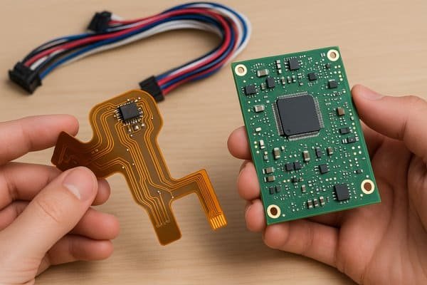
A flexible PCB is a printed circuit board fabricated on a bendable substrate, typically polyimide, with conductive copper traces laminated onto it. These boards can bend, fold, or flex during installation and operation while maintaining electrical connectivity, enabling three-dimensional circuit applications impossible with rigid boards.
Flexible PCBs fundamentally differ from their rigid counterparts in both materials and construction. While rigid PCBs use glass-reinforced epoxy (FR-4) providing structural stability, flex PCBs1 employ thin polyimide films2 (typically 25μm-125μm thick) that can bend repeatedly without breaking. The copper layers in flex PCBs are also thinner (often 0.5oz or 18μm) than standard rigid boards to enhance flexibility.
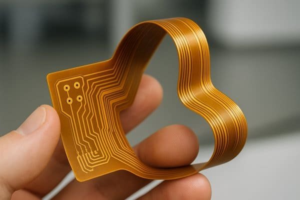
The base polyimide material offers exceptional properties beyond just flexibility: high temperature resistance (withstanding up to 400°C short-term), excellent chemical resistance, superior dimensional stability, and a dielectric constant of approximately 3.2-3.5 (slightly lower than FR-4's 4.0-4.5). This lower dielectric constant actually improves signal integrity in high-speed applications.
Manufacturing flex PCBs involves specialized processes. Rather than mechanical drilling, laser drilling3 creates vias in the thin materials. The copper is typically rolled-annealed rather than electrodeposited to prevent cracking during flexing. Most importantly, flexible PCBs require specialized design considerations including bend radii limitations (typically 6-10 times the material thickness), neutral bend axis planning, and controlled impedance routing that accounts for the mechanical stresses in bend areas.
When to Use Flex PCB?
My team once spent weeks trying to route a complex rigid PCB connection between two boards at right angles, only to discover that a simple flex circuit would have solved our problems in days while improving reliability.
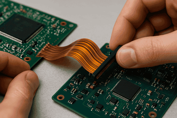
Flex PCBs are ideal when facing space constraints, weight restrictions, dynamic movement requirements, or complex three-dimensional installations. They excel in applications requiring high reliability in harsh environments, elimination of connector failures, improved thermal management, or reduced electromagnetic interference through consistent controlled-impedance traces.
Determining whether a flex PCB is the right solution involves evaluating several key application requirements. In my experience, flex circuits deliver the most value in specific scenarios where traditional rigid PCBs simply cannot perform adequately.
The primary application categories include dynamic flexing applications (where the circuit must bend during normal operation, like printer heads that move thousands of times), flex-to-install applications (bent once during assembly and remaining static afterward), and three-dimensional packaging requirements (where space constraints demand circuits that conform to unusual shapes).
According to IPC standards4 (particularly IPC-2223), flex circuits shine in demanding environments where reliability is critical. Military and aerospace applications leverage flex PCBs extensively because their monolithic construction eliminates failure-prone connectors and wire bonds. Medical devices, particularly implantables, benefit from flex PCBs' biocompatibility, miniaturization capabilities, and reliability where failure isn't an option.
Consumer electronics manufacturers have embraced flex PCBs to achieve increasingly thinner designs. For example, modern smartphones typically contain 8-12 separate flex circuits connecting various components while navigating extremely tight spaces. Automotive applications use flex PCBs behind dashboard instrumentation and in tight engine compartments where traditional wiring harnesses would be too bulky.
The decision framework should weigh electrical performance needs (signal integrity, impedance control), mechanical requirements (static vs. dynamic flexing, bend radii), environmental factors (temperature extremes, chemical exposure), production volumes (justifying higher tooling costs), and system-level benefits (reduced assembly complexity, higher reliability).
How Much Does a Flexible PCB Cost?
When budgeting my first flex PCB project, I experienced sticker shock until understanding the value equation – the higher material costs were offset by assembly savings and improved reliability that prevented expensive field failures.
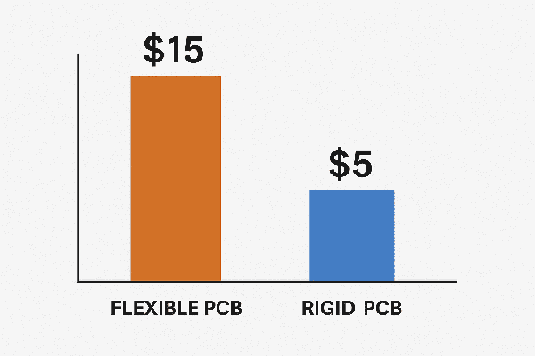
Flexible PCBs typically cost 3-10 times more than equivalent rigid boards, with pricing ranging from $2-5 per square inch for simple single-sided designs to $8-15 per square inch for double-sided flex with plated through-holes. Complex multi-layer flex designs can exceed $20 per square inch. These prices reflect higher material costs (polyimide vs. FR-4) and more specialized manufacturing processes.
Flex PCB pricing involves multiple variables that engineers must consider during early project planning. Based on data from IPC's Cost Analysis Service, material costs constitute approximately 35-50% of flex PCB pricing (versus 15-25% for rigid boards), making it the dominant cost driver. Polyimide substrate costs 5-8 times more than FR-4, while specialized cover layers and adhesives add further expense.
The manufacturing complexity significantly impacts pricing. According to a Manufacturing Engineering analysis, fabrication yield for flex PCBs5 typically ranges from 80-90% (compared to 95%+ for rigid boards), driving up costs as manufacturers build in yield loss considerations. Registration difficulties with thin, dimensionally unstable materials require more sophisticated equipment and processes.
The cost breakdown by complexity level, based on industry standard pricing models, shows:
- Single-sided flex: $2-5 per square inch (1-2 weeks lead time)
- Double-sided flex: $5-10 per square inch (2-3 weeks lead time)
- Multi-layer flex (3+ layers): $10-20+ per square inch (3-4 weeks lead time)
- Rigid-flex hybrid: $15-30+ per square inch (3-5 weeks lead time)
Quantity significantly affects pricing, with minimum order quantities often starting at $250-500 for prototype runs. Volume production (1,000+ pieces) can reduce per-unit costs by 40-60% compared to prototype pricing.
Project timelines also affect costs. Standard lead times average 2-3 weeks, while expedited manufacturing (3-5 days) typically incurs a 50-100% premium. The cost-benefit analysis must consider these factors alongside the substantial assembly savings flex PCBs often provide by eliminating connectors, reducing labor, and improving reliability.
What Is the Shelf Life of Flex PCB?
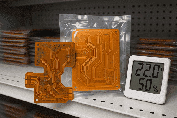
After discovering deteriorated flex PCBs in our inventory, I learned the importance of proper storage conditions – our climate-controlled stockroom wasn't enough without considering humidity control and packaging.
Properly stored flexible PCBs typically have a shelf life of 12 months according to IPC-1-A-610 standards. However, under ideal storage conditions (temperature 20-25°C, relative humidity 40-60%, oxygen and UV-protected packaging), manufacturers like DuPont and Panasonic report successful assembly of flex PCBs stored for 2-3 years without degradation in solderability or performance.
The shelf life of flex PCBs depends heavily on material considerations and storage conditions. The polyimide substrate itself is extremely stable, with DuPont Kapton®6 maintaining its physical properties for decades. However, the overall PCB's usability is primarily limited by metallization degradation – specifically copper oxidation and intermetallic growth that affect solderability.
According to IPC-1-A-6107 (Acceptability of Electronic Assemblies) and IPC-HDBK-001 (Handbook and Guide to Supplement J-STD-001), several factors accelerate flex PCB degradation:
- Temperature fluctuations: Causing expansion/contraction stresses at material interfaces
- Humidity exposure: Accelerating oxidation and potentially causing delamination
- Surface finish degradation: ENIG (Electroless Nickel Immersion Gold) finishes typically maintain solderability longer (12-18 months) than HASL (Hot Air Solder Leveling) finishes (6-12 months)
- Improper handling: Excessive bending or contamination from skin oils
The industry consensus on storage conditions specifies:- Temperature: 20-25°C (68-77°F)
- Relative humidity: 40-60%
- Packaging: Moisture barrier bags with desiccant and humidity indicator cards
- Protection from UV exposure and atmospheric contaminants
Most manufacturers implement a first-in-first-out (FIFO) inventory system with date coding to track shelf life. For critical applications, particularly in medical and aerospace fields, acceptance testing of older inventory (typically via solderability testing per J-STD-0028) is standard practice before use.
Extended storage is possible with vacuum-sealed moisture barrier packaging utilizing nitrogen purging, which can extend usable life to 3+ years according to testing by companies like 3M and Rogers Corporation. For flex PCBs with exposed pads, resurfacing processes like plasma cleaning can rejuvenate solderability of aged boards, though this adds cost and processing steps.
What Is the Difference Between Flexible and Rigid-Flex PCB?
When designing a complex medical device with severe space constraints, I initially specified separate rigid and flex PCBs until discovering that rigid-flex integration eliminated multiple connection points, dramatically improving reliability while simplifying assembly.
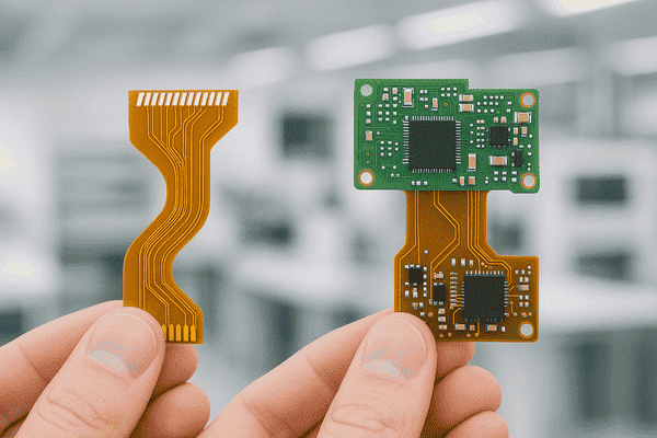
Flexible PCBs consist entirely of bendable materials (typically polyimide) and can flex throughout their entire surface area. Rigid-flex PCBs combine rigid board sections (FR-4 or similar) with flexible interconnecting sections in a unified laminated structure. While flex PCBs offer maximum flexibility at lower cost, rigid-flex provides the reliability benefits of flex with the component mounting stability of rigid boards.
Flexible and rigid-flex PCBs represent distinct design approaches with different manufacturing processes, capabilities, and cost implications. Understanding these differences helps determine which technology best fits specific application requirements.
Structurally, a flex PCB consists of a continuous flexible substrate (typically polyimide) with copper conductors and flexible coverlay (similar to solder mask on rigid boards). In contrast, rigid-flex PCBs feature multiple zones: rigid areas constructed with FR-4 or other traditional rigid materials, and flexible sections using polyimide. These sections are unified through a specialized lamination process that creates a single, integrated circuit board.
The manufacturing complexity differs significantly. Flex PCBs require fewer lamination cycles and typically involve 1-2 copper layers, though multi-layer flex designs exist. According to IPC-2223 (Sectional Design Standard for Flexible Printed Boards), the manufacturing yield decreases approximately 5-10% for each additional layer in flex designs. Rigid-flex manufacturing, governed by IPC-2223C guidelines, requires precise registration between rigid and flex sections, specialized techniques for layer transitions, and more complex lamination processes, resulting in significantly higher manufacturing costs.
Component mounting capabilities represent another key difference. Flex PCBs can accommodate components, but their flexibility makes them susceptible to component stress during flexing. Industry guidelines recommend mounting components at least 2-3mm from bend areas. Rigid-flex PCBs solve this problem by providing stable, non-flexing areas specifically designed for component placement, while restricting bending to the designated flexible sections.
The cost comparison between these technologies shows significant variations:
- Simple flex circuits: $2-10 per square inch
- Complex flex circuits (3+ layers): $10-20 per square inch
- Basic rigid-flex (2 rigid sections): $15-25 per square inch
- Complex rigid-flex (multiple rigid sections, 6+ layers): $25-50+ per square inch
These price differences reflect not just manufacturing complexity but also yield rates, which according to industry statistics are approximately 10-15% lower for rigid-flex compared to pure flex designs. However, rigid-flex often delivers substantial system-level cost savings through reduced assembly steps, fewer connectors, and improved reliability – especially important in high-reliability applications where field failures are extremely costly.
Conclusion
Flexible PCBs offer unique capabilities that solve complex design challenges, but come with higher costs and specialized design requirements. By understanding when and how to leverage their advantages, engineers can make informed decisions that balance performance, reliability, and cost.
-
Explore this link to understand the unique advantages and applications of flex PCBs compared to rigid ones. ↩
-
Learn about the properties and benefits of polyimide films in flexible PCB applications. ↩
-
Discover the innovative laser drilling process and its significance in creating flexible PCBs. ↩
-
Understanding IPC standards can help ensure compliance and quality in flex PCB manufacturing, crucial for reliability in critical applications. ↩
-
Learning about fabrication yield can help you assess the cost implications and quality of flex PCBs in your designs. ↩
-
Explore the unique properties of DuPont Kapton® that contribute to the longevity and stability of flex PCBs. ↩
-
Learn about IPC-1-A-610 standards to understand how they ensure the quality and reliability of electronic assemblies. ↩
-
Discover the significance of solderability testing in ensuring the reliability of older flex PCB inventory before use. ↩


