 Skip to content
Struggling with bulky, rigid electronics? Traditional designs limit innovation. Flexible PCBs unlock new possibilities for compact, dynamic products.
Flexible Printed Circuits (FPCs), or flex PCBs, are bendable electronic circuits built on pliable base materials instead of rigid ones. They enable electronics to fit into three-dimensional spaces, connect moving parts, and significantly reduce weight and volume, acting like a "flexible nervous system" for modern devices.
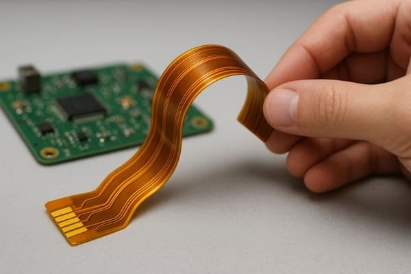
This capability to bend and conform isn't just a neat trick. It's a fundamental shift that allows us, as engineers, to think beyond flat planes. I’ve seen firsthand how this technology can transform a product concept from a clunky box into something sleek and ergonomic. But what exactly can you do with them, and where do they shine? Let's explore further.
What are flexible PCBs used for?
Are your product designs constrained by flat, stiff circuit boards? This often forces compromises in form factor and functionality. Flexible PCBs offer a way to integrate electronics into almost any shape.
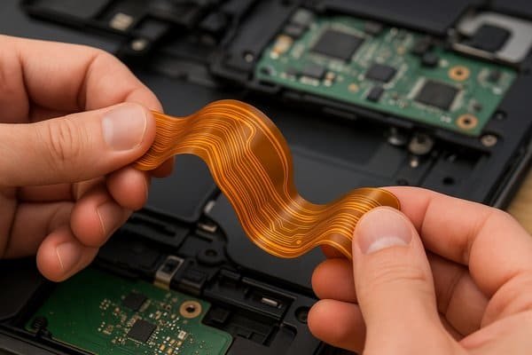
Flexible PCBs are primarily used for dynamic flexing applications, creating 3D interconnections, saving space and weight, and improving product reliability by eliminating connectors. They allow circuits to bend, twist, and conform to tight spaces where rigid boards cannot fit.
Unpacking the Core Applications of Flexible PCBs
The true value of a flexible PCB, as I see it, lies in its ability to enable extreme conformal integration and dynamic interconnection. Think of it: electronics that aren't confined to a single plane.
We can categorize their main uses like this:
| Application Area | Key Benefit of Flex PCB | Example Use Cases | Relevant IPC Standard Section |
|---|---|---|---|
| Dynamic Flexing | Reliable connection between parts moving relative to each other | Camera gimbals, foldable phone hinges, printer heads | IPC-22231 (Bend Radius) |
| 3D Interconnects | Conforms to complex product shapes, replaces bulky wires | Medical diagnostic tools, automotive dashboards, wearables | IPC-2223 (Formability) |
| Space/Weight Saving | Thinner, lighter materials enable miniaturization | Aerospace components, portable electronics, drones | - |
| Enhanced Reliability | Reduces connectors and solder joints, potential failure points | Devices in high-vibration or harsh environments | - |
For instance, in dynamic applications, like a robotic arm I once worked on, the flex circuit had to endure millions of bend cycles. We designed it according to IPC-2223 guidelines, ensuring the bend radius was at least 10 times the thickness of the flexible portion. For a 0.2mm thick flex, that meant a minimum 2mm bend radius. This careful design prevented copper trace fatigue and ensured long-term reliability.
Where are flexible PCBs used?
Wondering if these advanced circuits are right for your industry? Many sectors face challenges with space, weight, or reliability. Flexible PCBs often provide the ideal solution for these demanding environments.
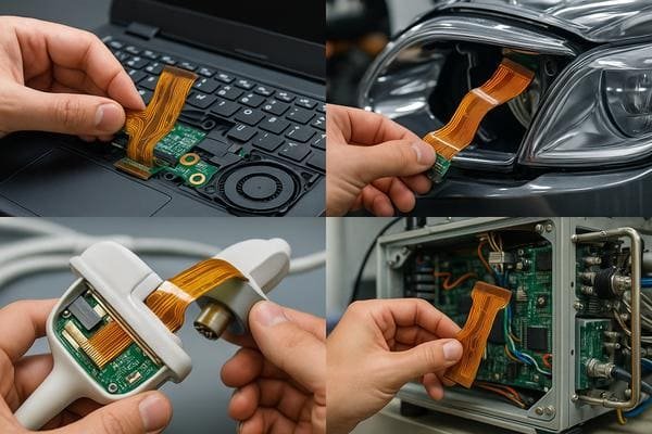
Flexible PCBs are used across a wide array of industries, including consumer electronics, automotive, medical, aerospace, defense, and industrial sectors. Their adaptability makes them suitable for applications requiring high reliability in compact or dynamic environments.
Industries Benefiting from Flexible PCB Technology
The adoption of flex PCBs is widespread because they solve fundamental engineering problems across diverse fields. I've seen their impact in so many areas.
Here's a look at some key industries:
| Industry Sector | Specific Use Examples with Flex PCBs | Key Drivers for Adopting Flex PCBs |
|---|---|---|
| Consumer Electronics | Smartphones (display, camera, battery), Laptops (hinge), Tablets, Wearables | Miniaturization, complex form factors, aesthetics |
| Medical Devices | Implantable devices, Endoscopes, Patient monitoring systems, Hearing aids | Biocompatibility, reliability, size, patient comfort |
| Automotive | Dashboard displays, Infotainment systems, Sensor modules, LED lighting strips | Space saving, vibration resistance, weight reduction |
| Aerospace & Defense | Avionics, Guidance systems, Satellite communications, Radar systems | Extreme reliability, weight reduction, harsh environments |
| Industrial | Robotics, Control panels in tight spaces, Test & Measurement equipment | Durability, custom shapes, reliable interconnections |
In the medical field, for a handheld diagnostic tool project, we used a complex rigid-flex PCB. The rigid sections held the microprocessors and critical sensors, while the flexible parts navigated the device's ergonomic curves, connecting to a display and buttons. This wouldn't have been possible with traditional boards and wires without making the device bulky and less user-friendly.
What electronic devices are commonly using flexible PCBs?
Curious about which specific gadgets benefit from this technology? Many everyday devices couldn't achieve their current form factor or functionality without them. Flexible PCBs are often hidden but essential components.
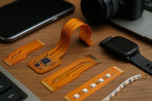
Common electronic devices using flexible PCBs include smartphones, laptops, digital cameras, printers, wearables (like smartwatches), medical implants, automotive displays, and LED lighting strips. Their presence is key to miniaturization and complex assemblies.
Everyday Devices: The Hidden Role of Flex PCBs
Let's break down a few common examples to see how flex PCBs make a difference. It's amazing how pervasive they are:
| Device Type | How Flex PCBs are Used | Key Benefit Achieved by Using Flex PCB |
|---|---|---|
| Smartphones & Tablets | Connecting main logic board to display, camera, battery, antennas | Enables ultra-thin profiles, complex internal assembly |
| Digital Cameras/Camcorders | Transmitting signals from moving lens elements to camera body | Allows for compact zoom/autofocus mechanisms |
| Laptops | Connecting motherboard to display (via hinge), keyboard, trackpad | Ensures durability over thousands of open/close cycles |
| Wearable Technology2 | Conforming to body contours, integrating sensors into small spaces | Improves ergonomics, comfort, and miniaturization |
| Printers | Connecting the moving print head to the main control board | Facilitates high-speed, repetitive, reliable motion |
| Automotive Displays3 | Linking display panels to control units in dashboards or seats | Fits into curved spaces, withstands vibration |
I remember taking apart an old inkjet printer years ago. The wide, flat flexible cable connecting the print head was a marvel of engineering to me at the time – it had to carry so much data and power while constantly whizzing back and forth. That was one of my early encounters appreciating the utility of flex circuits.
What is the difference between a flexible PCB and a rigid PCB?
Confused about when to choose flex over traditional rigid boards? Understanding their core differences is key to making the right design decision. They each have distinct advantages and trade-offs.
The main difference lies in their base material: flexible PCBs use pliable polymers like polyimide, allowing them to bend, while rigid PCBs use stiff materials like FR-4. This results in differences in application, cost, and mechanical properties.
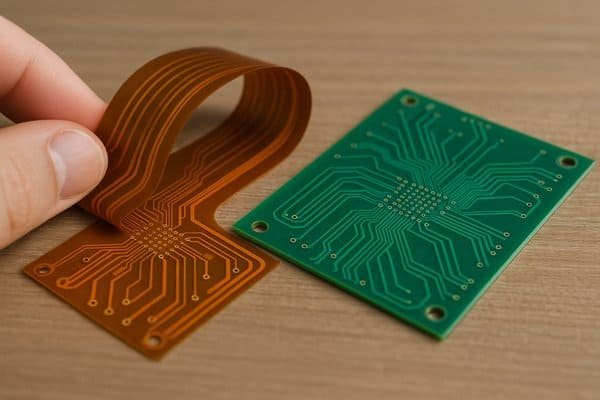
Flex vs. Rigid: A Detailed Comparison
While both serve to interconnect electronic components, their characteristics are quite distinct. I've had to weigh these differences on countless projects. Here's a more structured comparison:
| Feature | Flexible PCB (FPC) | Rigid PCB (e.g., FR-4) |
|---|---|---|
| Base Material | Polyimide (PI), Polyester (PET) | FR-4 (Flame Retardant Type 4 epoxy resin & glass fabric) |
| Flexibility | High; can be bent, folded, twisted (dynamic or static) | None; rigid and flat |
| Primary Use Case | Dynamic flexing, 3D interconnects, space/weight saving | Static, planar circuit mounting |
| Connectors | Can reduce or eliminate the need for connectors | Typically requires connectors for inter-board links |
| Weight | Generally lighter for the same circuit area | Generally heavier |
| Typical Thickness | 0.05mm to 0.4mm (single/double layer PI) | 0.2mm to 3.2mm+ (standard FR-4) |
| Vibration Resistance4 | Inherently better due to material damping | Can be prone to component stress from vibration |
| Relative Cost | Higher initial and per-unit cost | Lower initial and per-unit cost |
| Thermal Dissipation | Generally poorer without specific thermal management | Better, especially with thermal vias/planes |
| Repairability | More difficult to repair components | Easier to repair/rework components |
One critical decision point is often the "system-level" benefit. I might choose a more expensive flex or rigid-flex PCB if it eliminates three connectors and a complex wire harness, reducing assembly time and potential points of failure. This can make the overall product more reliable and sometimes even more cost-effective in the long run.
What material is used for flexible PCBs?
Curious about what makes these circuits bendy yet reliable? The choice of materials is critical to their performance and durability. It's not just any plastic; specialized polymers are key.
The most common base material for flexible PCBs is polyimide (PI), known for its excellent thermal stability, flexibility, and dielectric properties. Other materials include polyester (PET), various adhesives, and conductive copper foils.
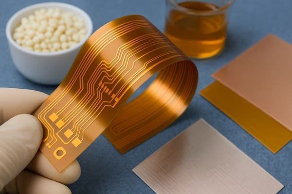
Core Materials in Flexible PCB Construction
The material stack-up in a flexible PCB is carefully engineered. Let's look at the main components:
| Component | Material Examples | Key Properties / Typical Values | Relevant IPC Standard(s) |
|---|---|---|---|
| Base Dielectric | Polyimide (PI), Polyester (PET) | PI: High temp. (-200°C to +300°C for Kapton®), flexible. PET: Lower cost, lower temp. (to ~100°C) | IPC-4202 (Base Dielectrics) |
| Conductive Material | Rolled Annealed (RA) Copper, Electro-Deposited (ED) Copper | RA Copper preferred for dynamic flex. ED for static. Common weights: 0.5 oz (18µm), 1 oz (35µm) | IPC-4562 (Metal Foils) |
| Adhesives | Epoxy, Acrylic; or Adhesiveless bonding | Must be flexible, withstand temperature cycling. Adhesiveless offers thinner, more flexible build. | IPC-4203 (Adhesive Films) |
| Coverlayer/Coverlay | Polyimide film with adhesive, Liquid Photoimageable (LPI) Ink | Protects circuitry, provides insulation. PI coverlay thickness: e.g., 25µm PI + 25µm adhesive. | IPC-SM-840 (Solder Mask) |
| Stiffeners | FR-4, Polyimide, Metal (e.g., Stainless Steel) | Provides local rigidity for component mounting or connector areas. Thickness varies. | - |
When I specify materials, especially for demanding applications like aerospace or medical, I refer to these IPC standards. For example, IPC-4202 Class B polyimide film offers a good balance of performance and cost for many applications. The choice between RA and ED copper is crucial for dynamic flex life; RA copper's elongated grain structure handles repeated bending much better.
How many layers can a flex PCB have?
Thinking about complex designs requiring multiple circuit layers? While flexibility is key, there are practical limits to layer counts. You need to balance complexity with manufacturability and reliability.
Flexible PCBs can range from single-sided (one conductive layer) up to 12 layers or more for complex designs. However, increasing layers reduces flexibility and raises costs, so most applications use 1 to 4 layers.
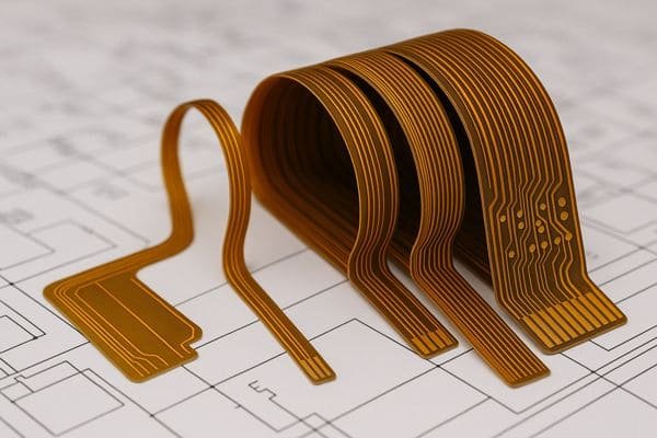
Understanding Layer Configurations in Flex PCBs
The number of layers in a flex PCB directly impacts its characteristics. Here's a general guide:
| Layer Type | Description | Typical Use Cases | Key Considerations |
|---|---|---|---|
| Single-Sided (1L) | One copper layer on one side of a dielectric film. | Basic interconnections, simple sensors, LED strips | Most flexible, lowest cost, simplest to manufacture. |
| Double-Sided (2L) | Two copper layers (one on each side of dielectric), usually with PTHs. | Higher routing density, display/camera connects | Good balance of flexibility and circuit density. |
| Multi-Layer (3L+) | Three or more copper layers laminated together with adhesive or adhesiveless bonding. | Complex circuits, controlled impedance, shielding | Reduced flexibility with each layer, higher cost, careful bend radius design needed (IPC-2223). Max practical usually 6-8 layers for pure flex. |
| Rigid-Flex | Combines rigid PCB sections with flexible interconnects. | Complex 3D assemblies, high-density components | Best of both worlds but most complex and costly. Can go to 12+ layers in rigid sections. |
In my experience, while I've seen designs claiming up to 20 layers for pure flex, these become extremely stiff (defeating the "flex" purpose) and incredibly expensive. For most practical flexible applications, 1 to 4 layers is the sweet spot. If more layers are needed with significant component density, I usually steer the design towards a rigid-flex solution. For instance, a 4-layer flex PCB might have a total thickness of around 0.2mm to 0.5mm, depending on copper weight and adhesive layers.
What are the limitations of a flexible PCB?
While offering many advantages, are there downsides to using flex PCBs? Yes, like any technology, they have limitations you must consider. It's not always the perfect solution for every problem.
Limitations of flexible PCBs include higher cost compared to rigid PCBs, lower current carrying capacity for the same trace width (due to thinner copper and heat dissipation), sensitivity to handling/tearing, and more complex design rules.
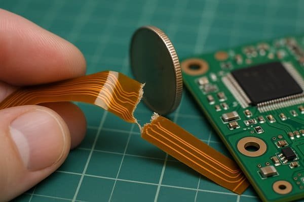
Acknowledging the Constraints of Flexible PCBs
From my experience designing with flex circuits, here are some key limitations to keep in mind:
| Limitation Category | Description | Impact / Consideration |
|---|---|---|
| Cost | Higher raw material costs (polyimide, specialized adhesives) and more complex manufacturing processes. | Can be 3x to 10x+ the cost of an equivalent rigid FR-4 board, especially in low volumes. |
| Current Carrying Capacity | Thinner copper layers (e.g., 0.5 oz) and poorer thermal dissipation of PI compared to FR-4. | Traces need to be wider for same current, or current must be derated. IPC-2152 gives guidance but derate further for flex. |
| Mechanical Handling | Thin materials can be prone to tearing or damage if mishandled, especially during assembly. | Requires careful handling procedures, strain relief at interfaces, possible use of stiffeners. |
| Design Complexity | Minimum bend radii must be respected (e.g., 6-10x thickness for static, 10-20x for dynamic). Component mounting often needs stiffeners. | Violating bend rules leads to failure. Stiffeners add cost and complexity. |
| Soldering & Rework | Soldering components can be tricky due to material flexibility and heat sensitivity. Rework is difficult. | Requires proper fixturing during assembly. Component replacement is challenging. |
| Signal Integrity | Maintaining controlled impedance on thin, flexible dielectrics can be harder. | Requires precise material control and etching; often limited to shorter trace lengths for very high speeds. |
I learned the hard way on an early project about tear strength. We had a sharp internal corner on a flex outline, and during assembly, a small tear started there and propagated. Now, I always ensure generous radii on all corners and consider tear-stop features if necessary, especially if the flex will be handled frequently.
Are flexible PCBs expensive?
Considering flexible PCBs for your next project, but worried about the budget? It's a common concern. The short answer is yes, they generally are.
Yes, flexible PCBs are typically more expensive than their rigid FR-4 counterparts. This is due to higher raw material costs (polyimide vs. FR-4) and more complex, specialized manufacturing processes.
Analyzing the Cost Factors of Flexible PCBs
When I’m architecting a new system, cost is always a major factor. While a direct flex-to-rigid cost comparison per square inch shows flex is pricier, it's important to look at the total system cost.
Here are the main drivers making flex PCBs more expensive:
| Cost Driver | Impact on Price | Example |
|---|---|---|
| Base Materials5 | Polyimide (Kapton® or equivalent) is significantly more costly than FR-4. | A sheet of PI film costs much more than an equivalent-sized FR-4 laminate. |
| Adhesives/Adhesiveless Tech | Specialized flexible adhesives or adhesiveless bonding processes add cost. | Acrylic or epoxy-based flex adhesives vs. standard FR-4 prepreg. |
| Manufacturing Complexity6 | Handling thin, flexible panels requires specialized equipment and care, often leading to lower yields. | Panelization, drilling, plating, and coverlay alignment are more delicate. |
| Tooling & Setup | Unique tooling (e.g., steel rule dies for outline cutting, specific fixtures) may be needed. | NRE (Non-Recurring Engineering) costs can be higher. |
| Reduced Panel Utilization | Flex circuits are often processed on smaller panels or with more waste material compared to large FR-4 panels. | Less efficient use of raw material sheets. |
| Added Features | Stiffeners (FR-4 or PI), PSAs (Pressure Sensitive Adhesives), shielding films, all add material and labor. | Each additional feature increases the bill of materials and assembly steps. |
However, it’s not just about the board cost. I've seen projects where using a single $20 flex PCB eliminated $5 worth of connectors, $3 of wiring harness, and $15 of assembly labor, actually reducing the total system cost while also improving reliability by removing potential failure points (the connectors and crimps).
How much does a flexible PCB cost?
Need a ballpark figure for flexible PCB costs? This is a tough question as prices vary wildly. However, I can give you an idea of the factors and some very general ranges.
Flexible PCB costs depend heavily on design complexity, materials, layer count, and volume. A simple single-layer prototype (e.g., 5cm x 5cm, 5-10 pieces) might start from $10-$70+ per board, while complex multi-layer flex can be hundreds per unit in low volumes.

Estimating Flexible PCB Costs: What to Expect
Giving an exact price for "a flexible PCB" is like asking "how much does a car cost?" – it depends entirely on the specifics. However, I can outline what drives the costs and offer some very broad examples based on my experience sourcing prototypes and production boards.
Example Cost Ranges (Very Approximate):
| Flex PCB Type & Volume (Typical Small Size e.g., 2x2 inches / 5x5 cm) | Estimated Cost Range (per piece, USD) | Key Assumptions / Notes |
|---|---|---|
| Prototype, Single-Layer (1L) (Qty: 5-10) | $10 - $70+ | Basic design, simple outline, standard polyimide, 1oz copper. |
| Prototype, Double-Layer (2L) (Qty: 5-10) | $20 - $100+ | Standard PTHs, PI coverlay. |
| Prototype, 4-Layer (4L) (Qty: 5-10) | $50 - $200+ | Or simpler 2L design with FR-4 stiffeners and PSA. |
| Low-Mid Volume, Simple 1L (Qty: 100s - low 1000s) | $2 - $15 | Significant NRE amortization, but still higher material/process cost. |
| Low-Mid Volume, Simple 2L (Qty: 100s - low 1000s) | $4 - $25 | |
| High Volume, Very Simple 1L (Qty: 10,000s+) | $0.50 - $5 | Highly optimized for mass production, often for consumer electronics. |
| Complex Rigid-Flex (e.g., 4L Rigid + 2L Flex) (Prototype Qty: 5-10) | $150 - $800+ | Combines both technologies, highest complexity and NRE. |
Disclaimer: These are very rough estimates. Prices are highly variable based on manufacturer, location, specific design features (fine lines, surface finish like ENIG, testing), and market conditions. Always get quotes for your specific design files (Gerber, BOM, fab drawing).
For instance, a simple single-layer flex for a battery connection, about 1cm x 3cm, might be $0.20 in very high volumes (millions), but a prototype run of 10 pieces could easily be $30 each due to setup costs.
Conclusion
Flexible PCBs offer unique advantages in modern electronics. They enable compact, dynamic, and three-dimensionally integrated designs, moving beyond the limits of traditional rigid boards.
-
Discover the IPC-2223 standard and its importance in ensuring the reliability and performance of flexible PCBs. ↩
-
Discover the innovative ways Flex PCBs improve wearable tech, enhancing comfort and functionality. ↩
-
Learn about the importance of Flex PCBs in automotive displays and their impact on design and durability. ↩
-
Discover the importance of vibration resistance in PCBs to ensure reliability in your electronic devices. ↩
-
Learning about base materials like polyimide can help you assess material costs in your PCB projects. ↩
-
Exploring manufacturing complexity will provide insights into the challenges and costs involved in producing flex PCBs. ↩


