 Skip to content
Struggling with mysterious noise, intermittent failures, or frustrating EMI/EMC compliance issues? The problem often isn't your core design, but your grounding strategy. This is more than a basic concept; it's a complex art that separates reliable products from problematic ones.
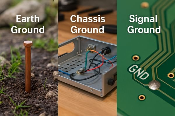
The key difference lies in their domain and purpose: Earth ground is a safety reference tied to the physical planet. Chassis ground is the shield and mechanical reference of the enclosure. Signal ground is the voltage reference and current return path for the electronics themselves.
After nearly two decades as a hardware engineer—from debugging high-pressure photonic computing boards to architecting globally-certified systems at Honeywell—I've learned that a robust grounding strategy is the bedrock of any successful product. It’s not just about connecting wires; it's about controlling current paths. Let's dive deep.
What Is An Electrical Ground?
Having trouble grasping what "ground" really means in a circuit? You're not alone. It's a simple concept that gets complicated fast.
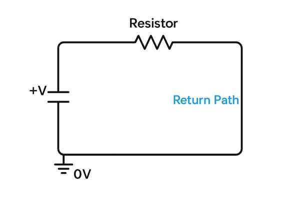
An electrical ground is a common reference point in a circuit from which all other voltages are measured. It's considered to have zero potential (0V) and serves as a return path for current.
Why Electrical Ground is a Dynamic System, Not an Ideal Node
For an experienced engineer, "ground" is not a static, ideal node. It's a dynamic physical structure with impedance. The key metric for a ground plane's effectiveness as a shield is its transfer impedance (\(Z_{t}\)). \(Z_{t}\) quantifies how much voltage appears on one side of the plane when a current flows on the other. A lower \(Z_{t}\) means better shielding. This is why a solid copper plane is far superior to a mesh or grid for shielding against high-frequency noise—its \(Z_{t}\) is significantly lower. Furthermore, the design priority changes with the application, requiring different approaches to ground design.
| Circuit Type | Primary Goal | Ground Design Priority | Key Concern |
|---|---|---|---|
| High-Power DC | Efficient Power Delivery | Minimize Resistance (\(R\)) (Wider Traces) | \(I^{2}R\) Power Loss, Thermal Hot Spots |
| High-Speed Digital | Preserve Signal Integrity | Minimize Inductance (\(L\)) (Unbroken Planes) | EMI, Crosstalk1, Reflections2 |
| Low-Noise Analog | Maintain High SNR3 | Minimize Shared Current Paths | Noise Coupling from \(V = I \times R\) Drops |
What Is The Symbol For Each Type Of Ground (Earth, Chassis, Signal)?
Confused by the different ground symbols on a schematic? Using the wrong one can lead to misinterpretation and design flaws. It's vital to know what each one represents.
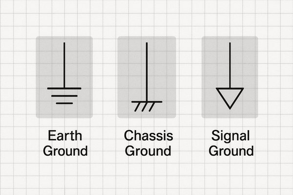
The earth ground symbol has three horizontal lines of decreasing length. The chassis ground symbol looks like a rake. The signal/common ground symbol is a triangle or three stacked horizontal lines.
Managing Ground Symbols in Professional EDA Tools
Beyond simple recognition, these symbols are powerful tools within an enterprise-level EDA environment (like Cadence or Altium). In the projects I've led, we configure our component libraries so that these symbols carry design intent. For example, a "chassis ground" symbol is not just a graphic; it's linked to a specific net class. This net class can have rules assigned to it, such as automatically ensuring a minimum clearance from signal nets or enforcing a connection to a specific type of plated mounting hole. This automates best practices and reduces human error.
| Ground Symbol | Standard Name | Expert Consideration in EDA Tools |
|---|---|---|
 | Earth Ground | Tie to the "Protective Earth" (PE) net class. Ensure connection only at the power entry. |
 | Chassis Ground4 | Assign to a net class with rules enforcing connection to plated mounting holes. |
 | Signal / Common | Use unique net names (AGND, DGND) to manage partitioning and connection strategies. |
Do All Circuits Need To Be Connected To Earth Ground?
Wondering if that battery-powered gadget you're designing needs a connection to a wall outlet's ground pin? It's a common point of confusion for new engineers.
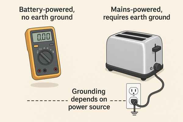
No, not all circuits require a connection to earth ground. Earth ground is primarily a safety feature for mains-powered equipment to prevent electric shock in case of a fault.
Earth Ground's Critical Role in Medical Device Safety
In the medical device field, grounding is a matter of life and death. The rules are dictated by IEC 60601-15, which defines classifications for "applied parts"—the components that physically touch the patient. Each has incredibly strict limits on leakage current6—the current that can flow through the patient to ground. Achieving these limits, especially for CF-rated devices, requires multiple layers of high-quality galvanic isolation.
| IEC 60601-1 Classification | Intended Use | Max Leakage (Normal) | Max Leakage (Single Fault) |
|---|---|---|---|
| Type B (Body) | General patient contact | \(< 100 \text{ µA}\) | \(< 500 \text{ µA}\) |
| Type BF (Body Floating) | Insulated patient contact | \(< 100 \text{ µA}\) | \(< 500 \text{ µA}\) |
| Type CF (Cardiac Floating) | Direct heart contact | \(< 10 \text{ µA}\) | \(< 50 \text{ µA}\) |
How Do You Properly Connect Chassis Ground To Earth Ground?
Connecting your product's metal case to earth ground seems simple, but getting it wrong can create safety hazards and EMI problems. It’s more than just running a wire.
The chassis should be connected to the earth ground pin of the power inlet using a dedicated, low-impedance connection. This connection must be robust and reliable, often using a specific screw or stud.
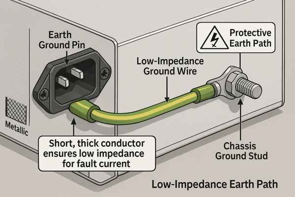
Ensuring a Reliable Long-Term Chassis-to-Earth Connection
For a product designed to last years, the long-term integrity of this connection is paramount. A common failure point is galvanic corrosion7. If you use a steel screw to connect a copper lug to an aluminum chassis, you've created a battery. In the presence of moisture, the more active metal (aluminum) will corrode, increasing the resistance of the ground connection over time. Choosing compatible materials is crucial.
| Component | Common Material | Key Consideration for Reliability |
|---|---|---|
| Grounding Screw | Green-dyed, zinc-plated steel | Use a dedicated thread-forming screw with a star washer to cut through paint/anodization. |
| Ring Terminal | Tin-plated Copper | Plating prevents oxidation and improves conductivity. Ensure proper crimping. |
| Chassis | Anodized Aluminum / Painted Steel | The connection point must be masked before finishing, or a star washer must be used. |
| Wire | Stranded Copper (Green/Yellow) | Must be of sufficient gauge (e.g., 18 AWG) and securely fastened to prevent vibration fatigue. |
What Is The Difference Between A Floating Ground and An Earth Ground?
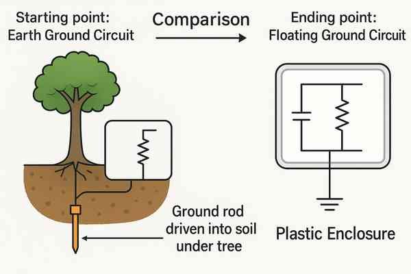
You've probably heard the term "floating ground" but might be unsure how it differs from the familiar earth ground. This distinction is crucial for both safety and circuit functionality.
An earth ground is a physical connection to the Earth, acting as a universal safety reference. A floating ground is a circuit's isolated reference point that has no direct connection to earth ground.
Using Floating Grounds to Reject Common-Mode Voltage
In industrial automation, floating and isolated inputs are essential for noise immunity. A factory floor is an incredibly noisy electrical environment. Variable Frequency Drives (VFDs) for motors can induce hundreds of volts of high-frequency common-mode voltage8 onto signal cables. If you try to measure a sensor with a standard, earth-referenced input, this common-mode voltage can saturate or destroy the input amplifier. By using an isolated front-end (a floating ground for the sensor circuit), the measurement system can tolerate this large voltage difference between its local ground and the sensor's ground. The amplifier then only measures the small differential signal from the sensor itself. For a control system I designed for an automated assembly line, we specified a minimum of 1500 Vrms isolation on all analog and digital I/O to ensure reliable operation amidst dozens of large motors.
How Should Signal Ground And Chassis Ground Be Connected?
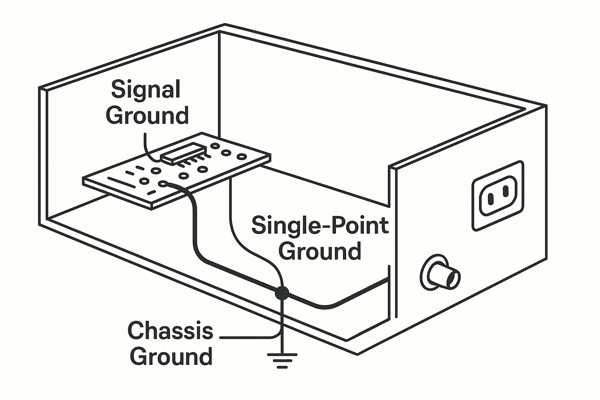
Connecting signal and chassis grounds is a critical design decision that impacts noise performance and safety. Do you connect them everywhere, at one point, or not at all?
Signal ground and chassis ground should typically be connected at a single point, usually near where the signals or power enter the enclosure. This prevents noisy chassis currents from flowing through the sensitive signal ground.
An Advanced Strategy for Connecting Signal and Chassis Grounds
For complex mixed-signal systems, the optimal strategy depends on the frequencies you need to control. A "hybrid" approach often provides the best performance across the spectrum by steering currents based on their frequency.
| Grounding Strategy | How It Works | Ideal Frequency Range | Best For |
|---|---|---|---|
| Single-Point | Connects signal and chassis grounds at one location. | DC to \(\approx 1 \text{ MHz}\) | Low-frequency analog, audio, power supplies. |
| Multi-Point | Connects grounds at many locations via low-inductance paths. | \(> 10 \text{ MHz}\) | High-speed digital and RF systems. |
| Hybrid | Uses a ferrite at the main connection and capacitors elsewhere. | DC to GHz | Complex mixed-signal systems needing both safety and EMI control. |
The hybrid strategy uses a grounding ferrite bead at the main connection point. This provides a low-impedance path for safety at DC/low-frequencies but becomes high-impedance at high frequencies, forcing noise to find a path through strategically placed capacitors (e.g., \(1 \text{ nF}\)) instead.
What Is A Ground Loop?
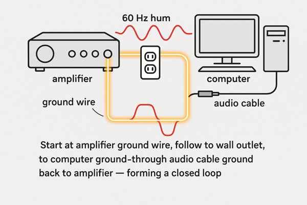
Ever hear a persistent 60 Hz hum from your audio system? You've likely encountered a ground loop. It's a common and frustrating problem for engineers and hobbyists alike.
A ground loop occurs when there are multiple paths to ground, creating a loop. This loop acts like an antenna, picking up noise (often 50/60 Hz hum from power lines) which is injected into your system.
Choosing the Optimal Solution to Fix a Ground Loop
Fixing a ground loop is about breaking the loop or making it immune to noise. The best solution depends on the specific problem. For differential signaling, the key to its effectiveness is the Common Mode Rejection Ratio9 (CMRR) of the receiver. To maximize CMRR, the layout of the differential pair is critical.
| Ground Loop Fix | How It Works | Expert Consideration & Trade-Offs |
|---|---|---|
| Single Power Strip | Minimizes potential differences between grounds. | Simple and effective, but doesn't solve loops from non-power connections (e.g., cable TV). |
| Audio Isolation Transformer | Galvanically isolates the ground path. | Excellent for audio. Check transformer specs for bandwidth and distortion. Not for DC signals. |
| Lifting the Shield | Disconnects the shield at one end of the cable. | A last resort. Breaks the loop but can severely compromise shielding against RF interference. |
| Differential Signaling10 | Uses a balanced pair to cancel common-mode noise. | The professional solution. Requires tight layout control (matched length/impedance) to maintain high CMRR. |
What Is The Difference Between Analog Ground (AGND) and Digital Ground (DGND)?
Working on a mixed-signal board with both analog and digital components? You'll see AGND and DGND. Treating them as the same can introduce a world of noise problems.
AGND is the return path for sensitive, low-level analog signals, while DGND is the return path for noisy, fast-switching digital currents. They are separated to prevent digital noise from corrupting analog signals.
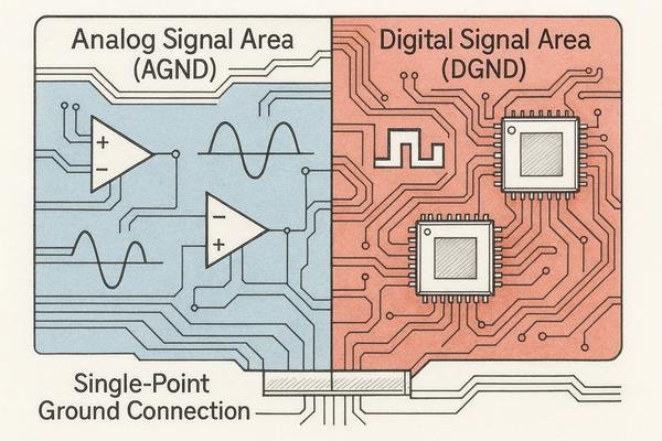
Advanced Partitioning for Analog and Digital Grounds
The idea of completely splitting the ground plane11 is a dangerous myth. The professional solution is to partition a solid ground plane and carefully manage the boundary.
| Technique | Description | Why It's Important |
|---|---|---|
| Partitioning | Place analog and digital components in separate areas of the board. | Keeps noisy digital return currents away from sensitive analog circuits. |
| Bridging | Connect AGND and DGND partitions at only one point, creating a "bridge." | Establishes a single, controlled reference point (usually at the ADC/DAC). |
| Routing Discipline | Never route a trace across the gap between partitions. Route all crossing traces over the bridge. | Prevents the signal's return current from forming a large, noisy loop. |
| Stitching | If a trace must cross a gap, add adjacent ground vias to "stitch" the grounds together. | Provides a short, local return path for high-frequency currents, minimizing EMI. |
What Is A Star Ground Configuration?
You need to connect multiple ground points, but how do you do it without creating noise problems? A star ground configuration is a classic and highly effective solution.
A star ground configuration is a wiring technique where all ground connections are brought back to a single, central point. This prevents return currents from different subsystems from interacting with each other.
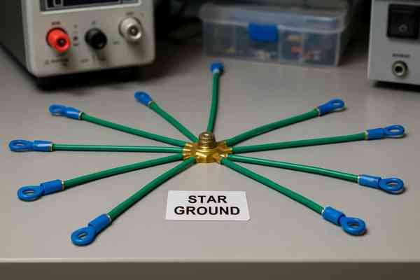
Understanding the High-Frequency Limits of Star Grounding
Star grounding is the optimal topology for preventing low-frequency current interaction. But its effectiveness collapses at high frequencies. The determining factor is the wavelength of the signal and the physical length of the connections. A solid ground plane becomes superior when inductance is the primary concern.
| Grounding Method | Primary Advantage | Ideal Frequency | Key Limitation |
|---|---|---|---|
| Star Grounding | Prevents shared current paths. | DC to \(\approx 1 \text{ MHz}\) | High inductance in the long connecting traces. |
| Solid Ground Plane | Provides a low-inductance return path. | \(> 1 \text{ MHz}\) | Requires careful component placement to manage return currents. |
A common rule of thumb is the \(\frac{\lambda}{20}\) rule: if a trace length is longer than one-twentieth of the signal's highest frequency component's wavelength (\(\lambda\)), it must be treated as a transmission line with a controlled-impedance12 return path, which a solid ground plane provides.
Conclusion
Mastering grounding moves beyond rules of thumb into a deep understanding of physics and system-level interactions. It's about meticulously controlling return currents, managing impedance, and making conscious design trade-offs to ensure safety, signal integrity, and regulatory compliance.
-
Learn how crosstalk affects signal integrity in high-speed digital circuits and discover effective strategies to reduce interference and improve performance. ↩
-
Learn how signal reflections can degrade high-speed digital signals, causing data errors and EMI, and discover best practices to minimize these issues. ↩
-
Understanding SNR is crucial for optimizing analog circuit performance and ensuring high-quality signal processing in low-noise applications. ↩
-
Explore this link to understand how to effectively implement Chassis Ground in your designs, ensuring compliance and functionality. ↩
-
Understanding IEC 60601-1 is crucial for ensuring medical device safety and compliance with international standards. ↩
-
Exploring leakage current helps grasp its impact on patient safety and device performance in medical settings. ↩
-
Understanding galvanic corrosion is essential for ensuring long-lasting connections in electrical systems. ↩
-
Understanding common-mode voltage is crucial for designing robust systems in noisy environments, ensuring reliable sensor measurements. ↩
-
Understanding CMRR is crucial for effective differential signaling and noise reduction in audio systems. ↩
-
Exploring differential signaling can enhance your knowledge of noise cancellation techniques in various applications. ↩
-
Learn why splitting the ground plane can cause signal integrity issues and discover best practices for analog and digital ground management. ↩
-
Learn how controlled-impedance ensures signal integrity in high-frequency circuits, crucial for preventing data loss and maintaining performance in your designs. ↩


