 Skip to content
Struggling with floppy flex circuits causing connector issues or component damage? Need a reliable way to add support exactly where needed for better assembly and reliability?
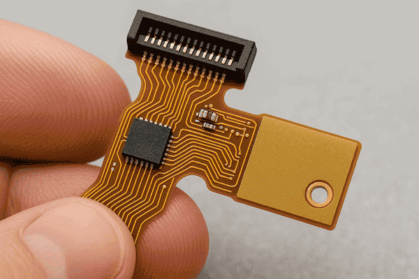
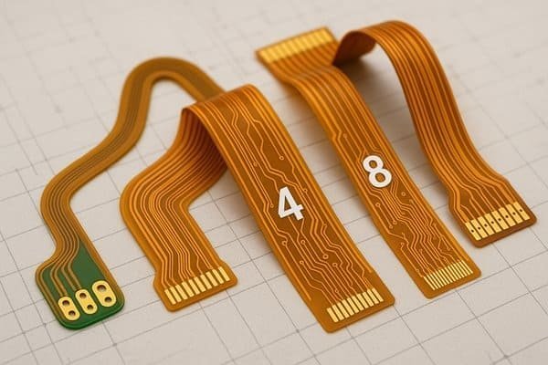
A flex PCB stiffener isn't just reinforcement; it's a functional rigidity enhancement. Using materials like FR-4 or polyimide, it's selectively bonded to provide mechanical support, precise thickness, and reliable mounting points, embodying a rigid-flex synergy crucial for robust designs.
Stiffeners might seem like a minor detail, but from my experience, they are fundamental to making flexible circuits work effectively in demanding applications. They bridge the gap between pure flexibility and the need for mechanical stability. Understanding how they fit into the broader PCB landscape is key, so let's look at how flex circuits compare to their rigid counterparts.
What is the difference between flex and non-flex PCB?
Confused about when to use a flexible circuit versus a standard rigid board? Choosing incorrectly can lead to designs that don't meet mechanical requirements or blow the budget.
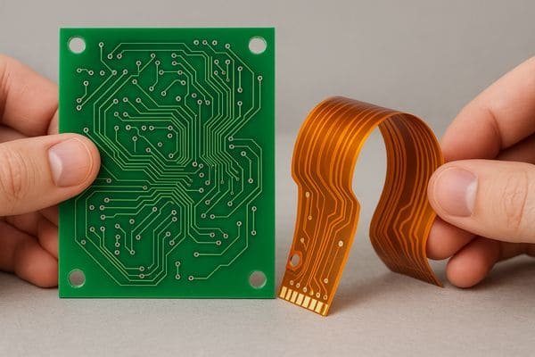
Non-flex (rigid) PCBs use solid substrates like FR-4, providing mechanical strength and stability. Flex PCBs use thin, pliable base materials like polyimide (PI), allowing them to bend, fold, and fit into complex three-dimensional spaces.
Diving Deeper: Flex vs. Rigid PCBs
The choice between a flexible and a rigid PCB fundamentally comes down to mechanical requirements and the operating environment. I've worked on projects using both, and the trade-offs are significant.
- Core Materials: Rigid boards typically use FR-4 (Flame Retardant 4), a glass-reinforced epoxy laminate, known for its rigidity, thermal performance (Tg around 130-180°C), and cost-effectiveness. Other rigid materials include CEM-1, CEM-3, or metal cores for thermal management. Flex PCBs primarily use Polyimide (PI)1, a polymer known for its excellent flexibility, thermal stability (can handle high soldering temperatures), and chemical resistance. Polyester (PET) is a lower-cost, lower-temperature alternative used in some simple flex circuits.
- Mechanical Properties: This is the most obvious difference. Rigid boards are designed to be flat and stiff. Flex circuits are designed to bend. The minimum bend radius2 for a flex circuit is a critical design parameter. According to IPC-2223C3 (Section 5.2.6), the minimum bend radius depends on the application (static vs. dynamic), layer count, and material thickness. For example, a single-layer static flex might tolerate a 6x thickness bend radius, while a multi-layer dynamic flex might require 20x-40x thickness or more.
- Construction: Flex circuit stackups are more complex, often involving adhesives to bond copper to the PI base, coverlays (flexible solder mask) for insulation, and potentially stiffeners (FR-4, PI, or metal) and pressure-sensitive adhesives (PSAs) for mounting. Rigid boards have a more straightforward layer lamination process.
- Cost: Flexible materials and the specialized processes required to handle them make flex circuits significantly more expensive per unit area than standard FR-4 boards.
Here’s a table summarizing the key differences:
| Feature | Rigid PCB | Flex PCB | Key Standard(s) |
|---|---|---|---|
| Base Material | FR-4, CEM, Metal Core | Polyimide (PI), Polyester (PET) | IPC-4101, IPC-4202 |
| Flexibility | None (intentionally) | High (designed to bend/fold) | IPC-2223C |
| Typical Cost | Lower | Higher (3x-10x+ vs Rigid) | - |
| Common Use Cases | Motherboards, Power Supplies | Wearables, Cameras, Medical, Automotive | - |
| Key Challenge | Fitting in non-flat spaces | Cost, Handling, Lower Dimensional Stability | - |
Understanding these fundamental differences is the first step in deciding if a flex circuit, potentially with stiffeners, is the right direction for your design.
What does a flex cut PCB do?
Heard the term "flex cut" but aren't sure what it means or achieves? Mistaking it for a true flex circuit can lead to designs that fail under mechanical stress.
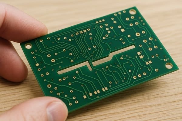
A "flex cut" usually refers to slots or cutouts milled into a standard rigid PCB (like FR-4). This creates a localized hinge, allowing limited bending between rigid sections, often for assembly purposes.
Diving Deeper: Understanding Flex Cuts in Rigid PCBs
It's important to clarify that a "flex cut" PCB isn't the same as a flexible PCB made from polyimide. I've seen this cause confusion before. The term typically describes a fabrication technique applied to a standard rigid board (usually FR-44) to introduce some localized bending.
- Purpose: The main goal is usually to allow a single rigid board to be bent during assembly to fit into an enclosure with non-planar surfaces, or to create a simple, static connection between two sections of the board without needing a separate cable or connector. Think of it as creating an integrated hinge.
- Mechanism: Material (the FR-4 substrate) is carefully removed, often by milling or routing, leaving behind only the copper traces (sometimes with a thin layer of remaining substrate or solder mask) spanning the cut area. This narrow bridge of copper allows the board to bend along the cut line.
- Limitations: This approach has significant limitations compared to true flex circuits:
- Limited Bend Radius: FR-4 is brittle. Bending too sharply will fracture the remaining substrate and stress the copper traces.
- Low Fatigue Life: These cuts are generally suitable only for static bends (bend once during installation). Repeated flexing (dynamic use) will quickly fatigue the copper traces, leading to cracks and circuit failure. True flex circuits are designed for thousands or millions of flex cycles.
- Stress Concentration: The ends of the cuts are points of high stress concentration, making them prone to cracking.
- No Specific Standard: While general PCB design rules apply, there isn't a specific IPC standard dedicated solely to the design and reliability testing of "flex cuts" in rigid boards like there is for true flex (IPC-2223C). It's more of a mechanical feature relying on careful empirical design.
- Design Considerations: Routing traces perpendicular to the bend line, using wider traces in the bend area, adding fillets or rounded corners at the ends of the cuts, and carefully defining the allowable bend angle and radius are crucial.
Essentially, a flex cut is a low-cost way to achieve a very limited bending capability on a rigid board for specific static applications. It's not a substitute for a proper flex or rigid-flex design when dynamic movement or tight bend radii are needed.
Which is better: flex cut or non-flex cut PCB?
Choosing between a standard rigid board and one with flex cuts? Making the wrong decision affects reliability, cost, and how easily your product can be assembled.
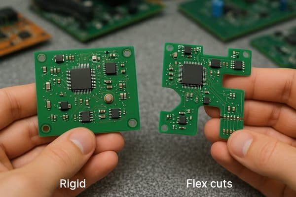
Neither is inherently "better"; the best choice depends entirely on the application's requirements. Standard rigid PCBs offer maximum robustness and cost-effectiveness for flat designs. Flex cuts provide limited bending for specific static assembly needs.
Diving Deeper: Choosing Between Rigid and Flex Cut Rigid PCBs
Selecting the right type of board construction is critical for project success. I always weigh the pros and cons based on the specific needs of the product.
- Application Fit:
- Non-Flex Cut (Standard Rigid): This is the default choice for most electronic applications where the PCB remains flat. It offers the best structural integrity, is ideal for high component densities, has well-understood design rules (e.g., IPC-2221), and is generally the most cost-effective option. Use this whenever bending isn't required.
- Flex Cut (in Rigid): Consider this option only when you need a single, static bend during assembly to fit the PCB into a specific enclosure shape or to create a simple, permanent angle between sections of the board. It might replace a small cable and two connectors in very cost-sensitive, high-volume applications where reliability requirements are not extreme.
- Reliability5: Standard rigid PCBs are inherently more robust. The introduction of flex cuts creates weak points. The copper traces spanning the cut are vulnerable to damage from over-bending, vibration, or shock. The ends of the cuts can initiate cracks in the FR-4 material. For any application involving movement, vibration, or multiple bend cycles, a flex cut rigid board is generally unsuitable. A true flex or rigid-flex PCB would be necessary.
- Cost: Adding flex cuts requires additional machining steps (routing/milling) compared to a standard rectangular rigid board, increasing the fabrication cost slightly. However, it's typically significantly cheaper than designing and manufacturing a true flexible PCB or a rigid-flex PCB. The potential cost saving comes from eliminating connectors and cables, but this must be balanced against the potential reliability risks.
- Performance: Signal integrity needs careful consideration. Routing high-speed signals across a flex cut requires analysis to ensure impedance control is maintained and that the trace geometry doesn't introduce unacceptable discontinuities or signal degradation.
Here’s a simple decision guide:
| Factor | Standard Rigid PCB Recommended When... | Flex Cut Rigid PCB Considered When... | Alternative to Consider |
|---|---|---|---|
| Flexibility Needs | None required. | Single static bend needed for assembly. | True Flex/Rigid-Flex |
| Reliability Needs | High robustness needed, vibration/shock present. | Low stress, static application, controlled environment. | True Flex/Rigid-Flex |
| Cost Target | Cost minimization is key (for the PCB itself). | Need lowest cost way to achieve a single bend (vs flex). | Cables/Connectors |
| Assembly | Standard flat assembly. | Need to fit board into angled/tight space. | True Flex/Rigid-Flex |
| Dynamic Movement | Not applicable. | Absolutely not suitable. | True Flex/Rigid-Flex |
In summary, use standard rigid PCBs whenever possible. Only consider flex cuts for very specific static bend requirements where cost is paramount and the reliability implications are acceptable. If you need true flexibility or repeated bending, invest in a proper flex or rigid-flex design.
How many layers can a flex PCB have?
Need complex routing in a flexible format but worried about layer count limitations? Exceeding practical limits can lead to manufacturing nightmares, high costs, and reduced flexibility.
Flex PCBs commonly range from 1 to 8 layers. While technically possible to manufacture flex circuits with 20+ layers, this dramatically increases cost, complexity, and significantly reduces the board's flexibility. Most applications use 1-4 layers.
Diving Deeper: Layer Count in Flexible PCBs
The number of layers you can incorporate into a flex PCB is a trade-off between routing density, cost, and mechanical performance. While manufacturers might advertise capabilities for very high layer counts6, practical designs usually stay within a more modest range.
- Common Practical Range: In my experience designing and working with manufacturers, the sweet spot for most commercial applications is between 1 and 8 layers.
- 1-2 Layers (Single/Double Sided): Very common for simple interconnects, display connections, membrane switches, basic sensors. Offers maximum flexibility and lowest cost.
- 3-4 Layers (Multi-Layer): Used when more complex routing, some impedance control, or basic shielding is needed. Common in wearables, medical devices, compact cameras. Flexibility starts to decrease noticeably.
- 5-8 Layers (Multi-Layer): Required for higher density routing, demanding signal integrity (e.g., controlled impedance lines between layers), or integrated shielding layers. Found in more complex medical devices, some automotive applications, and simpler rigid-flex constructions. Flexibility is significantly reduced.
- Technical Possibilities (High Layer Counts): Advanced manufacturers, particularly those serving military and aerospace sectors, can produce flex and especially rigid-flex circuits with 10, 15, 20, or even more layers. IPC-2223C acknowledges constructions beyond 10 layers. However, these are specialized, very expensive, and primarily used where space and weight savings are absolutely critical and cost is a secondary concern.
- Factors Limiting Practical Layer Count:
- Flexibility: This is the primary constraint. Each added layer (copper, adhesive, polyimide core) increases the overall thickness. Thicker circuits have a larger minimum bend radius and are much stiffer. IPC-2223C provides formulas showing bend radius increases with thickness. Exceeding the material's bend limits leads to failure.
- Manufacturing Complexity: Aligning and laminating multiple thin, flexible layers requires high precision. Dimensional stability of flex materials is lower than FR-4, making registration harder as layer count increases. Via formation (drilling and plating) through many flexible layers is also challenging.
- Cost: The cost increases significantly with each additional layer. It's not just the material cost but the added processing steps (lamination cycles, drilling, plating) and potentially lower yields.
- Reliability: More layers mean more interfaces and vias, increasing the potential points of failure, especially under mechanical stress or thermal cycling. Ensuring via reliability in thick flexible stacks is crucial.
When designing, always start with the minimum number of layers required for routing. If density demands more layers, carefully evaluate the impact on flexibility, cost, and manufacturability with your chosen fabrication partner. Often, optimizing the layout or considering a rigid-flex approach might be better than pushing flex layer counts too high.
How thick is a flex PCB?
Designing for tight spaces and need to know the precise thickness of a flex circuit? Getting this wrong can lead to mechanical interference, assembly headaches, or compromised flexibility.
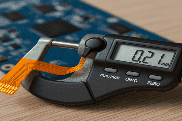
A typical single-layer flex PCB is around 0.1mm to 0.2mm (4-8 mils) thick. Double-layer flex circuits are often 0.2mm to 0.4mm (8-16 mils) thick. Thickness increases with layer count, copper weight, and the use of adhesives and stiffeners.
Diving Deeper: Understanding Flex PCB Thickness
The total thickness of a flexible printed circuit is the sum of its constituent layers. Unlike rigid boards where FR-4 cores dominate, flex PCB thickness is built up from multiple thin layers. Getting an accurate estimate requires knowing the specific materials used in the stack-up.
- Component Layers Contributing to Thickness:
- Base Material (Dielectric Core): Typically polyimide (PI). Common thicknesses specified in IPC-42027 (Flexible Base Dielectrics) are 12.5µm (0.5 mil), 25µm (1 mil), and 50µm (2 mil). Thinner bases offer more flexibility.
- Copper Foil: Bonded to the base material. Common weights are 0.5 oz (approx. 18µm or 0.7 mils), 1 oz (approx. 35µm or 1.4 mils), and sometimes 2 oz (approx. 70µm or 2.8 mils). Heavier copper increases thickness and significantly reduces flexibility. IPC-4562 covers metal foils.
- Adhesive: Used for bonding copper to the base (in adhesive-based constructions) and for laminating layers. Typical thicknesses range from 12.5µm to 50µm (0.5 - 2 mils). Common types are acrylic or epoxy based, covered by IPC-4203. Adhesiveless constructions8 (direct copper deposition/lamination) eliminate this layer between the base and initial copper, resulting in a thinner, more flexible build.
- Coverlay: A flexible insulating layer (like a flexible solder mask) applied over the outer copper traces. Usually consists of a polyimide film plus adhesive. Total thickness is often similar to the base material + adhesive, e.g., 25µm PI + 25µm adhesive = 50µm (2 mils). Covered by IPC-4204.
- Stiffeners (Optional): Add significant thickness locally. FR-4 stiffeners typically range from 0.2mm (8 mils) to 1.6mm (62 mils). Polyimide stiffeners are thinner, maybe 50µm to 125µm (2-5 mils).
- Example Thickness Calculation (Typical 1-Layer Flex):
- Coverlay (25µm PI + 25µm Adhesive): 50µm
- Copper (1 oz): 35µm
- Adhesive (if used): 25µm
- Base PI (1 mil): 25µm
- Approx. Total: 135µm (0.135mm or ~5.3 mils) - Common range: 0.1mm - 0.2mm
- Example Thickness Calculation (Typical 2-Layer Flex, Adhesiveless Base):
- Coverlay (25µm PI + 25µm Adhesive): 50µm
- Copper (1 oz): 35µm
- Base PI (1 mil, copper clad both sides): 25µm
- Copper (1 oz): 35µm
- Coverlay (25µm PI + 25µm Adhesive): 50µm
- Approx. Total: 195µm (0.195mm or ~7.7 mils) - Common range: 0.2mm - 0.4mm (using adhesives would add ~50µm)
Always consult your manufacturer's specifications and request a detailed stack-up drawing for precise thickness information, especially for multi-layer or impedance-controlled designs. IPC-2223C provides design guidelines related to material selection and thickness.
What is the adhesive in Flex PCB?
Wondering what exactly holds the layers of a flex circuit together and why it matters? Choosing or specifying the wrong adhesive can lead to delamination, reduced performance, or failure under stress.
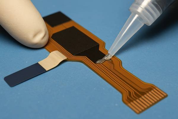
Adhesives in flex PCBs are specialized bonding agents, typically acrylic or epoxy based. They are used to laminate copper foil to the dielectric base material and to bond multiple layers together, including coverlays and stiffeners.
Diving Deeper: Adhesives in Flex Circuit Construction
Adhesives are a critical component in many flex PCB constructions, playing a vital role in structural integrity and performance. However, adhesiveless constructions are also common, particularly for higher-performance applications.
- Primary Functions:
- Copper-to-Base Bonding: In traditional "3-Layer" Flexible Copper Clad Laminate (FCCL), an adhesive layer bonds the copper foil to the polyimide base film.
- Layer Lamination: In multi-layer flex circuits, adhesive bonding films (often polyimide or epoxy coated with adhesive) are used to laminate the individual flex layers together.
- Coverlay Attachment: Adhesives bond the protective coverlay film (polyimide + adhesive) over the outer layer traces.
- Stiffener Attachment: Adhesives (often thermosetting or pressure-sensitive types) bond stiffeners (FR-4, PI, metal) to the flex circuit in specific areas.
- Common Adhesive Types (IPC-4203):
- Acrylic Adhesives: Generally offer good flexibility and lower cost. However, they typically have lower thermal resistance (max operating temps around 120-150°C) and can exhibit higher moisture absorption and Z-axis expansion compared to epoxies. Good for general-purpose, cost-sensitive applications.
- Epoxy Adhesives9: Provide higher temperature resistance (up to 150-180°C or more), better dimensional stability, and lower moisture absorption. They tend to be slightly more rigid than acrylics. Often preferred for higher layer counts, rigid-flex applications, or environments with higher temperatures or chemical exposure. Modified epoxies exist to improve flexibility.
- Pressure-Sensitive Adhesives (PSAs)10: Used primarily for attaching the finished flex circuit to a housing or mounting surface. Not typically used for core layer bonding. Various formulations exist (acrylic, silicone).
- Adhesiveless Construction ("2-Layer FCCL"):
- In this method, the copper layer is applied directly to the polyimide base film without a distinct adhesive layer (e.g., via casting, sputtering/plating, or direct lamination).
- Advantages: Thinner overall construction, improved flexibility (no adhesive layer stiffness), better thermal performance (direct copper-polyimide path), better dimensional stability (less Z-axis expansion), suitable for finer lines and spaces due to the smooth interface.
- Disadvantages: Generally higher material cost, potentially lower initial copper peel strength compared to some adhesive systems (though often sufficient for most applications). This is often preferred for demanding applications.
- Selection Criteria: Key factors when choosing an adhesive system (or deciding between adhesive vs. adhesiveless) include: required operating temperature, flexibility needs (bend radius, dynamic vs. static), number of layers, desired final thickness, cost target, and any environmental factors (moisture, chemicals). Always discuss these requirements with your PCB fabricator.
Is Flex PCB expensive?
Considering using flexible PCBs in your design but worried about the budget impact? Underestimating the cost difference compared to rigid boards can lead to unpleasant surprises later in the project.
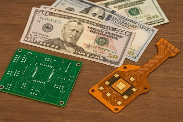
Yes, flex PCBs are significantly more expensive than standard rigid PCBs of equivalent size and layer count. Depending on complexity, the cost can be anywhere from 3 times to over 10 times higher.
Diving Deeper: Understanding Flex PCB Cost Drivers
While flex circuits offer compelling advantages in packaging and reliability for certain applications, these benefits come at a higher price point compared to traditional FR-4 boards. I always make sure this cost difference is understood early in the design phase.
- Key Cost Drivers:
- Raw Materials: Polyimide films, flexible adhesives, and coverlay materials specified in standards like IPC-4202, IPC-4203, and IPC-4204 are inherently more expensive than the FR-4 epoxy/glass C-stage and prepreg used in rigid boards (IPC-4101).
- Manufacturing Processes: Handling thin, flexible materials requires specialized equipment and care. Processes like roll-to-roll handling (for high volume) or carrier systems for panel processing, precise alignment for coverlay and layer lamination, plasma etching for via cleaning, and stiffener application are more complex and time-consuming than rigid board processes.
- Yield Rates11: Flexible materials exhibit lower dimensional stability during processing (they can stretch or shrink more than FR-4). This makes achieving tight tolerances and high yields more challenging, especially for multi-layer designs or those with very fine features (lines/spaces < 75µm or 3 mils). Lower yields directly translate to higher unit costs.
- Labor and Inspection: Flex circuits may require more manual handling, specialized inspection techniques (e.g., for coverlay alignment or stiffener placement), and potentially more complex electrical testing fixtures.
- Added Features: Complexity significantly impacts cost. Features like stiffeners, Pressure Sensitive Adhesives (PSAs), controlled impedance requirements, shielding films, and specialized surface finishes all add to the final price.
- Relative Cost Comparison (Illustrative):
- Single-Sided Rigid FR-4: 1x (Baseline)
- Double-Sided Rigid FR-4: ~1.2x - 1.5x
- Single-Sided Flex (PI, Adhesive-based): ~3x - 6x
- Double-Sided Flex (PI, Adhesive-based): ~5x - 10x
- 4-Layer Flex (PI): ~8x - 15x+
- 4-Layer Rigid-Flex (2 Rigid + 2 Flex Layers): ~10x - 20x+
(Disclaimer: These are rough estimations for discussion. Actual costs depend heavily on the specific design geometry, features, tolerances, volume, chosen manufacturer, and market conditions. Always get specific quotes.)
- Justifying the Cost: Despite the higher unit price, flex PCBs can sometimes lead to lower total system cost by:
- Eliminating connectors, cables, and associated assembly labor.
- Reducing assembly time and potential connection errors.
- Enabling smaller, lighter, and more uniquely shaped product designs.
- Improving reliability by removing failure-prone electromechanical connections, especially in vibrating or dynamic applications.
When considering flex, perform a thorough cost-benefit analysis comparing the higher flex PCB cost against potential savings in components, assembly, and improved product form factor or reliability.
What is the best tool to cut PCB?
Need to cut or depanelize PCBs, either prototypes or production batches, but unsure which tool is safest and most effective? Using the wrong method can damage boards, stress components, or create hazardous debris.
For industrial depaneling, CNC routing or V-groove scoring/breaking are standard. For manual cutting or prototype modification, a specialized PCB nibbler, a rotary tool (like Dremel) with appropriate bits, or sometimes a shear are used.

Diving Deeper: Tools and Methods for Cutting PCBs
The "best" tool depends heavily on the context: are you separating boards from a production panel, modifying a prototype, cutting rigid FR-4, or trimming a flexible circuit? Safety and quality of the cut edge are key considerations.
- Production Depanelization (High Volume):
- V-Groove Scoring & Breaking: A V-shaped cut is made partially through the board on both sides. Boards are then snapped apart manually or using a fixture. It's fast and low-cost for straight-line separation but puts mechanical stress on components near the edge. IPC-A-610 and J-STD-001 have guidelines on component proximity to V-grooves to minimize stress damage.
- CNC Routing/Milling12: A high-speed router bit cuts the board outline precisely. Allows complex shapes (curves, internal cutouts) and creates less stress than V-scoring. Requires "breakaway tabs" or fixtures to hold the board during routing. Generates significant fiberglass dust (requires vacuum extraction).
- Laser Cutting13: Uses a focused laser beam to ablate or melt the material. Very precise, minimal mechanical stress, suitable for complex shapes and delicate components. Can be used for both rigid and flex PCBs. Higher equipment cost.
- Punching/Die Cutting: A custom die punches the board shape out. Very fast and low cost per unit after high initial tooling investment. Best suited for extremely high volumes of a stable design. Less common for typical complex PCBs.
- Manual Cutting & Prototype Modification (Low Volume/Lab):
- PCB Nibbler14: A hand tool that takes small (~1.5mm x 3mm) rectangular "bites" out of the board. Allows cutting irregular shapes and internal cutouts with minimal dust and stress. Relatively slow process and leaves a somewhat ragged edge. Good for FR-4 up to ~1.6mm.
- Rotary Tool (e.g., Dremel): Equipped with abrasive cut-off wheels (e.g., fiberglass reinforced) or small carbide milling bits. Versatile and fast for straight or curved cuts in FR-4. Generates significant abrasive dust - mandatory use of safety glasses and dust mask/extraction is critical. Can generate heat. Risk of delamination if not careful.
- PCB Shear/Guillotine: Benchtop tool providing clean, straight cuts, similar to a paper cutter but much stronger. Good for quickly cutting FR-4 blanks down to size. Not suitable for populated boards or complex shapes.
- Hacksaw/Jigsaw: Generally not recommended for precision work. Creates very rough edges, lots of dust, high risk of damaging traces or components. Use only as a last resort for rough cutting.
- Cutting Flexible PCBs: Flex circuits are often cut using methods that minimize tearing or stress:
- Laser Cutting: Very common for precision cutting of flex outlines and features.
- Die Cutting: Used for high-volume production of specific shapes.
- Specialized Blades/Plotters: Knife-based cutting systems can be used.
- Avoid coarse mechanical methods like shears or saws.
- Safety First: Always wear safety glasses when cutting PCBs. When using rotary tools, routers, or saws that generate dust from FR-4 (fiberglass/epoxy composite), use appropriate respiratory protection (N95 mask or better) and dust extraction systems to avoid inhaling harmful particles.
Conclusion
Flex PCB stiffeners are essential engineering elements, providing localized rigidity where needed. Understanding their function, alongside the differences between flex, rigid, and flex-cut boards, helps create robust and cost-effective electronic designs.
-
Explore the advantages of Polyimide in flexible PCBs, including its thermal stability and flexibility, which are crucial for modern electronics. ↩
-
Understanding the minimum bend radius is essential for designing reliable flex circuits that can withstand bending without damage. ↩
-
Learn about IPC-2223C, a key standard for flex circuit design, which provides guidelines for bend radius and other critical parameters. ↩
-
Learning about FR-4 material will provide insights into its applications and limitations in PCB manufacturing. ↩
-
Learn about the importance of reliability in PCB design and how it influences material selection and construction methods for better performance. ↩
-
Understanding the optimal layer count can help you balance performance and cost in your PCB designs. ↩
-
Learn about IPC-4202 standards for flexible base dielectrics, crucial for understanding material specifications in flex PCBs. ↩
-
Discover how adhesiveless constructions enhance flexibility and reduce thickness in flexible printed circuits. ↩
-
Learn about the benefits of epoxy adhesives, including their high temperature resistance and dimensional stability for flex PCBs. ↩
-
Discover how PSAs are utilized in flex PCB manufacturing and their role in attaching circuits to surfaces. ↩
-
Yield rates are crucial in determining the final cost of flex circuits; understanding them can aid in better budgeting and planning. ↩
-
Explore the benefits of CNC Routing/Milling for precise PCB cutting, including reduced mechanical stress and complex shapes. ↩
-
Learn about Laser Cutting's precision and minimal stress on components, making it ideal for both rigid and flexible PCBs. ↩
-
Discover how a PCB Nibbler can help in making irregular cuts with minimal dust, perfect for low-volume modifications. ↩


