 Skip to content
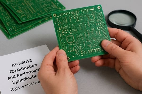
Struggling with inconsistent PCB quality? Worried about field failures? Understanding IPC-6012 is key to getting reliable rigid boards that meet your design intent every single time.
IPC-6012 defines the quality and performance requirements for rigid printed circuit boards. It sets acceptance criteria for materials, fabrication processes, and final board characteristics, ensuring reliability based on defined performance classes (Class 1, 2, 3, 3A).
So, we know IPC-6012 is important for rigid boards. But how does it fit into the bigger picture of IPC standards, and what specific details matter most for engineers like us? Let's dive deeper into the specifics.
What is the IPC standard for PCB?
Feeling lost in the sea of IPC documents? Unsure which standard applies to your specific board type? Let's clarify the landscape.
The "IPC standard for PCB" isn't one document. It's a family of standards covering design (IPC-2220 series), materials (IPC-4101), rigid boards (IPC-6012), flex circuits (IPC-6013), assembly (IPC-A-610), and more, ensuring consistency across the electronics industry.
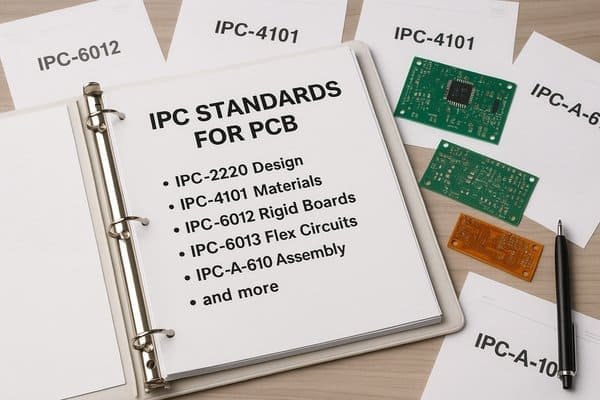
Think of IPC standards as a comprehensive library. They cover the entire lifecycle of a printed circuit board. The IPC-2220 series1 gives general design principles. Specific standards like IPC-2221 (Generic), IPC-2222 (Rigid), and IPC-2223 (Flex) provide detailed design rules. Material specifications are in standards like IPC-41012 for laminates. Then come performance standards such as IPC-6012 for rigid boards, IPC-6013 for flex circuits, and IPC-6018 for high-frequency boards. These define what a good bare board looks like after manufacturing. Finally, IPC-A-610 covers how components should be assembled. Here's a quick summary:
| Standard Category | Key IPC Examples | Primary Focus |
|---|---|---|
| Design | IPC-2221 (Generic), IPC-2222 (Rigid), IPC-2223 (Flex) | PCB layout rules, features, stack-up details |
| Materials | IPC-4101 (Laminates & Prepregs) | Properties of raw materials used in PCB fabrication |
| Performance (Bare Board) | IPC-6011 (Generic), IPC-6012 (Rigid), IPC-6013 (Flex) | Acceptance criteria for manufactured bare boards |
| Assembly | IPC-A-610 (Acceptability), J-STD-001 (Requirements) | Component placement, soldering, cleaning |
IPC-6012 acts as a critical bridge for rigid boards. It translates design rules and material choices into measurable acceptance criteria for the fabricator. It ensures the physical board meets the intended performance and reliability.
What is the IPC 6012 summary?
Need a quick overview of IPC-6012? Overwhelmed by the full document's detail? Let's break down the essentials you need to know.
IPC-6012 summarizes the qualification and performance specifications for rigid PCBs. It covers visual inspection criteria, dimensional tolerances, structural integrity requirements (like plating thickness, layer registration), electrical properties, and environmental testing protocols, categorized by performance classes (1, 2, 3/3A).
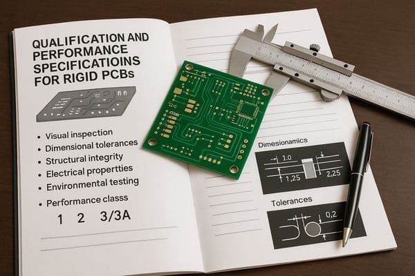
IPC-6012 provides a full framework for rigid PCB quality. It's not just a final checklist. It defines the agreement between designer and fabricator. Key areas include:
| IPC-6012 Key Area | Examples of Criteria Covered | Importance for Designers |
|---|---|---|
| Visual & Dimensional | Surface quality (scratches, pits), solder mask registration, hole size/position accuracy, board outline. | Ensures manufacturability, component fit, and acceptable appearance. |
| Structural Integrity | Layer-to-layer registration, plating thickness (PTH, surface), annular ring, dielectric spacing, laminate voids. | Critical for long-term reliability, withstanding assembly stresses, and proper electrical function. |
| Electrical Requirements | Continuity (verifying no opens), Isolation (verifying no shorts), minimum insulation resistance. | Verifies the basic electrical functionality of the printed circuit board. |
| Cleanliness & Solderability | Maximum ionic contamination levels, integrity of solderable finishes. | Crucial for reliable soldering processes, preventing future corrosion and electrochemical migration. |
As I see it, its real power comes when used during design. It should be a core input for DFM (Design for Manufacturability3) and DFS (Design for Solderability). By designing to IPC-6012 requirements for your chosen class, you address potential manufacturing issues early. This ensures reliability instead of just finding problems later. It turns abstract goals like "high reliability" into measurable targets.
What is the difference between IPC 6012 and 6011?
Confused between IPC-6011 and IPC-6012? They sound similar, but cover different ground. Let's clarify the distinction for your PCB projects.
IPC-6011 is the generic performance specification for all printed boards (rigid, flex, rigid-flex). IPC-6012 is a specific standard that builds upon 6011, detailing the requirements only for rigid PCBs. Think of 6011 as the parent, 6012 as the child for rigid boards.
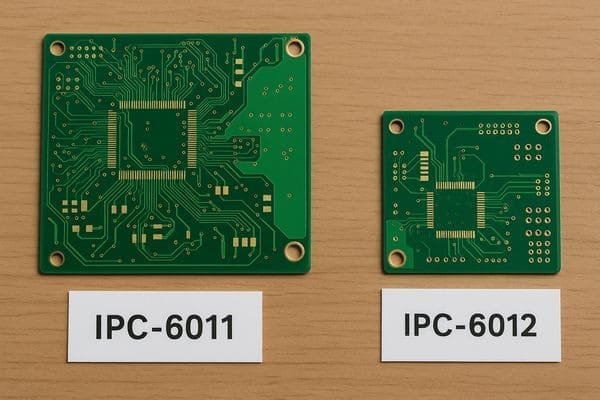
The relationship between IPC-6011 and IPC-6012 is hierarchical. IPC-6011, Generic Performance Specification for Printed Boards, sets baseline requirements for all types of printed boards. It establishes the general framework, defines performance classes (Class 1, 2, 3), outlines qualification, and references common test methods (from IPC-TM-650). IPC-6012, Qualification and Performance Specification for Rigid Printed Boards, adds specific requirements for rigid boards.
| Feature | IPC-6011 | IPC-6012 |
|---|---|---|
| Scope | Generic (Applies to All PCB types) | Specific (Applies to Rigid PCBs only) |
| Detail Level | General requirements and classifications | Detailed requirements for rigid board characteristics |
| Relationship | Parent/Foundation Standard | Child/Specific Standard (builds on 6011 for rigid) |
| Typical Use Case | Establishes baseline for all PCB performance | Primary performance specification for rigid FR-4 boards |
IPC-6012 details aspects like PTH integrity under thermal stress4, specific criteria for rigid laminates, and tighter tolerances for rigid board features. If you're designing a standard rigid PCB, you primarily work with IPC-6012. It incorporates relevant principles from IPC-6011, so you don't typically reference IPC-6011 directly for a purely rigid board.
What is the difference between IPC-A-600 and 6012?
Seeing both IPC-A-600 and IPC-6012 mentioned? Wondering how they relate? They serve different but complementary purposes in ensuring PCB quality.
IPC-6012 defines the performance requirements and specifications a rigid PCB must meet. IPC-A-600 provides the visual interpretation and acceptance criteria for those requirements. Think of 6012 as the rulebook, and A-600 as the illustrated guide for inspection.
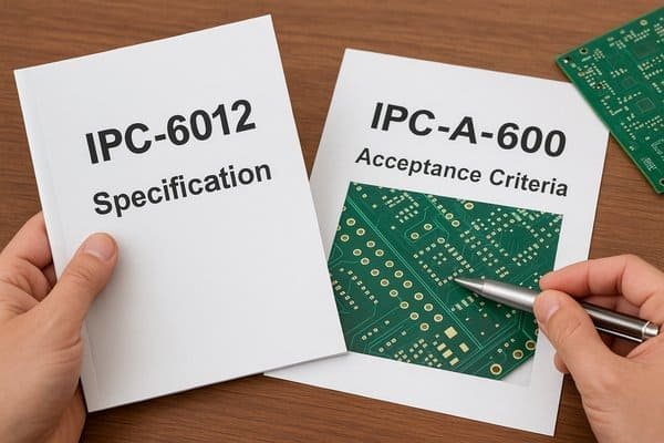
IPC-6012 and IPC-A-600 are often used together. IPC-6012 lays down the rules. It defines minimum performance specifications5 and qualification requirements. It sets measurable criteria like minimum copper plating in vias (e.g., 20µm average for Class 2 per IPC-6012F Table 3-5), void limits in vias, dielectric spacing, and annular ring needs. IPC-A-600, Acceptability of Printed Boards, is the visual guide for these specs. It shows photos and illustrations for "Target," "Acceptable," and "Non-conforming" conditions found in IPC-6012.
| Aspect | IPC-6012 | IPC-A-600 |
|---|---|---|
| Primary Function | Defines performance requirements & specs | Provides visual interpretation6 & acceptance criteria |
| Content Nature | Rulebook (quantitative values, e.g., "20µm min") | Illustrated guide (pictures of good/bad features) |
| Primary User | Designers (to specify), Fabricators (to meet) | Inspectors, QA personnel (to visually verify acceptability) |
| Example | States: "Min. PTH plating average 20µm (Class 2)" | Shows photos: what an acceptable vs. non-conforming PTH plating looks like |
Engineers use IPC-6012 to specify quality. Inspectors use IPC-A-600 to visually verify if boards meet those requirements. You need IPC-6012 to understand the "why" behind IPC-A-600's visuals.
What is the difference between IPC 6012 and 6013?
Designing flex or rigid-flex circuits? Need to know if IPC-6012 applies? Understanding the difference between 6012 and 6013 is crucial here.
The difference is simple: IPC-6012 covers rigid printed boards (like standard FR-4 boards). IPC-6013 specifically addresses the qualification and performance requirements for flexible and rigid-flex printed boards, accounting for their unique materials and mechanical properties.
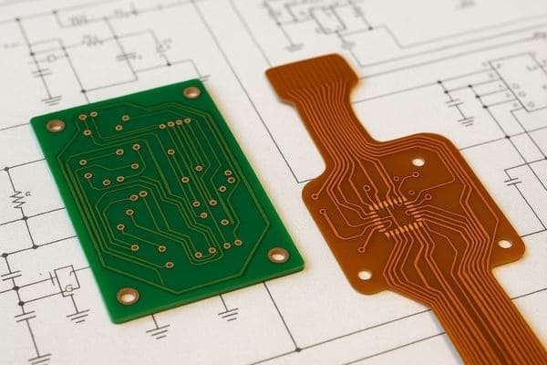
The core difference is the type of PCB technology they govern. IPC-6012 is for rigid printed boards (e.g., FR-4, CEM). IPC-6013 covers circuits designed to bend or fold, using materials like polyimide films. Flexible circuits have different materials, construction, and mechanical needs, so they need their own standard.
| Feature | IPC-6012 | IPC-6013 |
|---|---|---|
| Board Type | Rigid Printed Boards (e.g., FR-4) | Flexible and Rigid-Flex Printed Boards |
| Key Materials | FR-4, CEM, High-Tg laminates, rigid cores | Polyimide (PI), Polyester (PET), flexible adhesives, coverlays |
| Unique Focus Areas | General structural integrity, PTH quality for rigid materials | Flex endurance, bend radius, stiffener adhesion, transition zones (rigid-flex), coverlay integrity |
| Surface Covering | Typically Solder Mask | Typically Coverlay (flexible dielectric layer), sometimes flexible solder mask |
IPC-6013 addresses unique aspects like flex endurance7 (number of bend cycles), minimum bend radius, and criteria for transition zones in rigid-flex designs. If your project involves any flexible circuitry, IPC-6013 is your main performance standard. For rigid-flex, IPC-6013 governs the overall product, though IPC-6012 criteria might apply to the purely rigid sections.
What is the difference between IPC 6012 and 6018?
Working with high-frequency designs? Wondering if standard IPC-6012 is sufficient? Let's look at how IPC-6018 complements it for RF/microwave applications.
IPC-6012 covers general rigid PCBs. IPC-6018 specifically addresses the qualification and performance requirements for high-frequency (Microwave) printed boards, focusing on materials and features critical for maintaining signal integrity and performance at RF frequencies (typically >1 GHz).
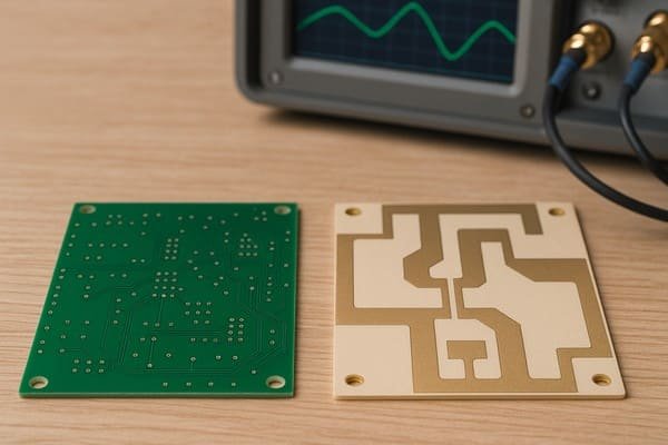
Both IPC-6012 and IPC-6018 deal with rigid boards, but their focus differs. IPC-6012 is for general-purpose rigid boards, often using FR-4 where dielectric properties have broader tolerances. IPC-6018, Microwave End Product Board Inspection and Test, is for boards in high-frequency applications (RF circuits, antennas). These designs are sensitive to material properties and manufacturing consistency.
| Feature | IPC-6012 | IPC-6018 |
|---|---|---|
| Application Focus | General Purpose Rigid PCBs | High-Frequency / Microwave Rigid PCBs (typically >1 GHz) |
| Material Emphasis | Standard laminates (e.g., FR-4) | Low-loss RF laminates (e.g., Rogers, Taconic), with tight control on Dk/Df |
| Key Concerns | General reliability, manufacturability | Signal integrity, precise impedance control, low signal loss at RF frequencies |
| Typical Requirements | Standard plating, dimensional tolerances | Tighter impedance tolerance (e.g., ±5%), specific surface finishes (ENIG, ENEPIG), Dk/Df verification |
IPC-6018 emphasizes specialized low-loss RF laminates8, stricter Dk/Df consistency, tighter impedance control (e.g., ±5%), and surface finishes like ENIG for better RF performance. If your design needs precise impedance and minimal loss at high frequencies, specify IPC-6018 compliance along with the appropriate IPC-6012 class.
What is the difference between IPC 6012 Class 2 and Class 3?
Specified IPC Class 2 or Class 3? Unsure what the real difference means for your board? This distinction impacts reliability, cost, and manufacturing complexity.
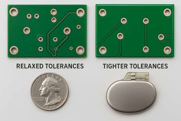
IPC Class 2 (Dedicated Service Electronic Products) allows for more relaxed tolerances and cosmetic imperfections. IPC Class 3 (High Performance/Harsh Environment) demands tighter tolerances, higher reliability, and stricter acceptance criteria, suitable for critical applications like aerospace or medical devices where failure is unacceptable.
The main difference is the intended service environment and acceptable failure risk. This leads to stricter criteria for Class 3.
- Class 2 (Dedicated Service Electronic Products): For most commercial and industrial electronics like computers and instruments. Reliable performance is expected, but failures are not life-critical.
- Class 3 (High Performance/Harsh Environment Electronic Products): For applications where failure is severe – aerospace, medical life support. Continuous high performance is key.
Here’s a table with key differences from IPC-6012F:
| Feature | Class 2 Requirement (Typical Example from IPC-6012F) | Class 3 Requirement (Typical Example from IPC-6012F) | Impact & Why it Matters |
|---|---|---|---|
| Annular Ring (External PTH) | May allow 90° breakout (tangency is acceptable, 3.3.4) | Requires minimum 0.05mm (≈2 mil) annular ring (3.3.4) | Ensures better solder fillet formation and via pad integrity |
| Annular Ring (Internal PTH) | May allow 180° breakout (tangency for lands, 3.3.5) | Requires minimum 0.025mm (≈1 mil) annular ring (3.3.5) | Prevents internal layer connection failures |
| Plating Thickness (PTH Cu)9 | Minimum average 20µm (≈0.79 mil) (Table 3-5) | Minimum average 25µm (≈0.98 mil) (Table 3-5) | Enhances via reliability under thermal stress/cycling |
| Dielectric Removal (Wicking) | More allowance for wicking into hole wall (3.3.9) | Tighter control on wicking distance (3.3.9) | Reduces potential for shorts or compromised insulation |
Specifying Class 3 increases manufacturing challenges and inspection, raising costs. Choose the class truly needed by the application.
How thick is the solder mask on IPC-6012?
Need to know solder mask thickness specs? Worried about mask coverage over traces or in tight spaces? IPC-6012 provides guidelines, but it's nuanced.
IPC-6012 itself doesn't mandate a specific solder mask thickness value. Instead, it focuses on functional requirements: adequate coverage over conductors, adherence, and proper curing. Typical thicknesses range from 0.4 to 1.5 mils (10-38 µm) over bare laminate.
IPC-6012 emphasizes solder mask performance, not a fixed thickness. The mask must provide insulation, adhere well, and be fully cured (Section 3.7.1 of IPC-6012F). Adhesion is often checked per IPC-TM-650, Method 2.4.28.1. While IPC-6012 doesn't give a number, IPC-SM-84010 covers mask material properties. For Liquid Photoimageable (LPI) solder mask, typical thicknesses are:
| Solder Mask Location | Typical Thickness Range (LPI Mask) | Key IPC-6012 Focus (Functional) |
|---|---|---|
| Over Bare Laminate | 0.4 - 1.5 mils (10 - 38 µm) | Adhesion (3.7.1.2), Curing (3.7.1.1) |
| Over Conductors (Traces) | 0.3 - 1.0 mils (8 - 25 µm) approx. | Coverage (3.7.1), No exposed copper (3.7.1.4) |
| Between Pads (Solder Dams) | Variable, must prevent solder bridging | Integrity, No Mask on Pad (3.7.1.3) |
Note: Thickness over conductors is inherently less due to topography. Source for ranges: General industry practice for LPI masks. Specific values from IPC-SM-840 focus on material qualification, not as-applied thickness on board.
Actual thickness varies. Discuss critical mask needs, especially dams between fine-pitch pads, with your fabricator.
What is the minimum dielectric thickness for IPC 6012?
Concerned about high voltage isolation or impedance control? Wondering about minimum dielectric spacing? IPC-6012 sets baseline requirements, but design needs often dictate more.
IPC-6012 specifies minimum dielectric spacing requirements based on voltage and performance class, often referencing design rules from IPC-2221. For common internal layers (Class 2), minimum spacing might be around ≥ 3.5 mils (89 µm), but impedance or voltage needs usually demand more.
IPC-6012 verifies dielectric spacing (Section 3.5.3), but specific minimums come from design standards like IPC-2221. IPC-2221B, Table 6-1 details conductor spacing for isolation.
| Voltage Range (DC/AC peak) | Performance Class | Min. Internal Spacing (Coated, Type B2) | Source for Design Rule |
|---|---|---|---|
| 0 - 15 V | Class 1, 2 | 0.05 mm (≈2 mils) | IPC-2221B, Table 6-1 |
| 0 - 15 V | Class 3 | 0.10 mm (≈4 mils) | IPC-2221B, Table 6-1 |
| 16 - 30 V | Class 1, 2 | 0.05 mm (≈2 mils) | IPC-2221B, Table 6-1 |
| 16 - 30 V | Class 3 | 0.10 mm (≈4 mils) | IPC-2221B, Table 6-1 |
Note: These are basic isolation minimums from IPC-2221B (B2 = Internal conductors, coated). External or uncoated conductors have different values. Altitude also affects spacing.
In my experience, these minimums are rarely the main factor. Dielectric thickness is usually driven by controlled impedance needs, high voltage safety (e.g., per IEC/UL 62368-1), or stack-up mechanical requirements. You must define these in your fabrication data.
What is the aspect ratio of IPC 6012?
Drilling small vias in thick boards? Worried about plating quality? Aspect ratio is a critical manufacturability limit, though not explicitly defined by IPC-6012 itself.
IPC-6012 doesn't mandate a specific maximum aspect ratio (Board Thickness / Smallest Drilled Hole Diameter). Instead, it sets performance requirements for plated through-holes (like minimum plating thickness and void limits) which implicitly limit the achievable aspect ratio based on a fabricator's capability.
Aspect Ratio (AR)11 = Board Thickness / Smallest Drilled Hole. IPC-6012 doesn't state a max AR. It focuses on PTH quality: minimum copper plating (e.g., Class 2: 20µm avg, IPC-6012F Table 3-5) and void limits (IPC-6012F 3.3.10). Achieving these is harder at high AR due to plating solution "throwing power."
| Fabricator Capability Level | Typical Aspect Ratio (AR) Range | Plating Challenge | IPC-6012 Compliance Likelihood |
|---|---|---|---|
| Standard | 8:1 to 10:1 | Manageable | Consistently meets plating thickness/void criteria |
| Advanced | 12:1 to 15:1 | Significant | Requires optimized processes and tight control |
| Leading Edge / Prototype | >15:1 (e.g., up to 18:1+) | Very High / Difficult | Higher risk of non-conformance, increased cost |
Source: General PCB fabrication industry capability ranges. These are not IPC-defined limits.
The practical AR limit is set by a fabricator's ability to meet IPC-6012 plating standards. Always confirm your fabricator's AR capability for your specific via size and board thickness before finalizing your design.
Conclusion
IPC-6012 is the essential standard defining quality and performance for rigid PCBs. Understanding its classes, scope, and relationship to inspection guides like IPC-A-600 ensures reliable boards meeting your design intent.
-
Explore this link to understand the foundational principles of PCB design outlined in the IPC-2220 series, crucial for any electronics engineer. ↩
-
Discover the detailed material specifications in IPC-4101, essential for ensuring quality in PCB fabrication and performance. ↩
-
Understanding DFM can significantly enhance your PCB design process, ensuring better manufacturability and reliability. ↩
-
Learn about the importance of PTH integrity in maintaining PCB reliability, especially under thermal conditions, a key aspect of IPC-6012. ↩
-
Understanding performance specifications is crucial for ensuring quality in PCB manufacturing. Explore this link to gain insights into IPC-6012's standards. ↩
-
Visual interpretation is key for quality assurance in PCBs. Discover how IPC-A-600 illustrates these standards effectively. ↩
-
Discover the importance of flex endurance in flexible circuits to ensure reliability and performance in your designs. ↩
-
Discover the benefits and applications of low-loss RF laminates, essential for high-frequency PCB performance. ↩
-
Plating thickness directly impacts the reliability and performance of electronic components, making it a key factor in design. ↩
-
IPC-SM-840 provides vital information on solder mask material properties, ensuring optimal performance in PCB applications. Check it out for detailed insights. ↩
-
Understanding the importance of Aspect Ratio (AR) can help you optimize your PCB design for better performance and compliance. ↩


