 Skip to content
Your PCBAs passed inspection, but what happens when they fail in the real world? This unexpected failure can derail project timelines and ruin budgets, causing major headaches for your team.
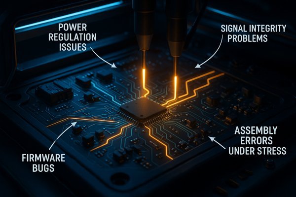
A functional test (FCT) is your final quality gate. It identifies critical flaws that visual and in-circuit tests miss, verifying that the PCBA behaves exactly as designed. It finds power regulation issues, signal integrity problems, firmware bugs, and subtle assembly errors that only appear under operational stress.
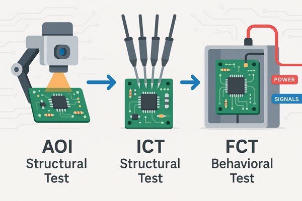
Functional testing is more than just another step in the process; it's the ultimate confirmation that your product works. While other tests check if the board was built correctly, FCT answers the most important question: does the board function correctly? It simulates the end-user environment to ensure the hardware, firmware, and software all work together seamlessly. Without it, you're essentially shipping a product hoping that it works, rather than knowing that it does. The table below shows how FCT fits in with other common tests.
| Test Method | Primary Focus | Example Defects Found |
|---|---|---|
| AOI (Visual) | Physical Assembly | Missing/Wrong Component, Solder Bridges, Polarity |
| ICT (Structural) | Electrical Connections | Shorts, Opens, Incorrect Resistor/Capacitor Values |
| FCT (Behavioral) | System Performance | Incorrect Voltage, Firmware Boot Failure, High Power Draw |
What Is Functional Testing (FCT) for PCBAs?
Worried that your newly assembled boards won't work once they're powered on? This is a common fear, where seemingly perfect boards fail to perform their basic functions.
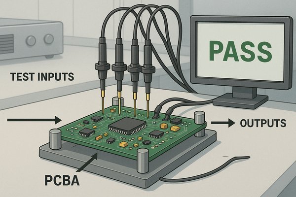
Functional testing, or FCT, is a black-box test that powers up and operates a PCBA to verify it behaves as intended. It simulates the final product's environment, feeding it specific inputs and checking for the correct outputs, ensuring every function works perfectly before it leaves the factory.
As a hardware engineer, I think of FCT as the board's first real job interview. It’s where the PCBA has to prove it can do what it was designed for. This is done using a custom test fixture, often called a "bed of nails" jig. This fixture securely holds the PCBA and makes all the necessary electrical connections through pogo pins or connectors.
The Anatomy of a Functional Test Setup
A typical FCT setup has several key parts that work together:
- The Fixture: This is the mechanical heart of the test. Fixtures range from simple manual "clamshell" designs for low-volume runs to fully automated inline systems that accept PCBAs from a conveyor belt. The design must ensure precise, repeatable contact with pogo pins on designated test points. This is why Design for Testability (DFT)1 is so crucial; from the start of the project, I ensure we have accessible test points for all power rails, critical signals, and programming ports.
- Test Instrumentation: This includes the equipment that provides inputs and measures outputs. Common instruments are programmable power supplies, digital multimeters (DMMs), oscilloscopes, signal generators, electronic loads, and communication interfaces like CAN bus or Ethernet controllers.
- Control & Automation Software: A PC running software like LabVIEW, Python with a DAQ card, or a dedicated test executive like TestStand controls the entire process. The software sequences the tests, sets instrument parameters, reads measurements, and compares them against predefined limits to give a final PASS or FAIL verdict. It also logs all test data for traceability and statistical process control.
Defining Pass/Fail Criteria for Functional Tests
The pass/fail criteria are the most critical part of the test plan. They are derived directly from the product's design specifications. For example, if a voltage regulator is supposed to output 3.3V with a ±5% tolerance, the FCT software will fail the board if the measured voltage is outside the 3.135V to 3.465V range. For a communications port, the test might involve sending 1 million data packets and ensuring zero errors are received back—any bit error results in a failure. This rigorous, automated check ensures every board meets its required performance specifications.
What Is the Difference Between Functional Testing (FCT) and In-Circuit Testing (ICT)?
Are you confused about whether you need ICT, FCT, or both? Choosing the wrong test strategy can mean either missing critical defects or spending too much on redundant testing.
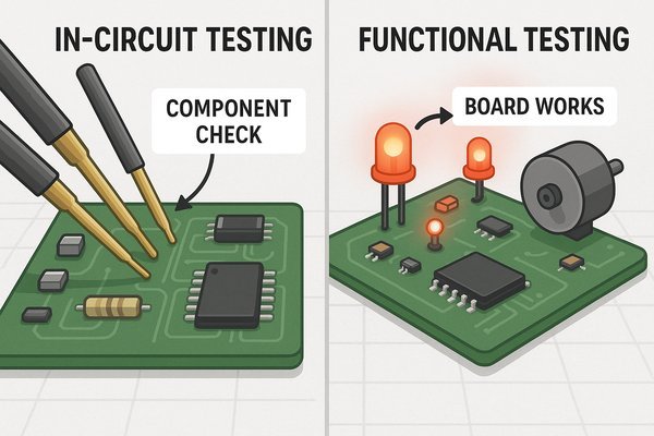
The key difference is simple: In-Circuit Testing (ICT) verifies that the board was assembled correctly by checking individual components. Functional Testing (FCT) verifies that the board works correctly by testing its overall behavior. ICT finds manufacturing defects, while FCT finds functional and performance-related defects.
Thinking of ICT and FCT as competing technologies is a mistake. They are complementary. I once worked on a project where a batch of boards kept passing ICT but failing FCT. The FCT showed that a communication bus was failing intermittently. After hours of debugging, we found that the wrong value capacitor was used on the bus termination. ICT passed it because the capacitor was functionally a capacitor, but FCT caught it because the incorrect value was corrupting the signals on the bus. This is a perfect example of why you need both.
Head-to-Head Comparison: ICT vs. FCT
| Feature | In-Circuit Test (ICT) | Functional Test (FCT) |
|---|---|---|
| Primary Goal | Find manufacturing defects (shorts, opens, wrong/missing components). | Verify the PCBA functions according to design specifications. |
| Test Method | Powers down the board and tests components in isolation using a bed-of-nails fixture. | Powers up the board and simulates its real operating environment. |
| Coverage | Verifies the "schematic." Typically achieves 85-98% nodal coverage. | Verifies the "specification." Tests specific functions like boot-up, communication, sensor readings. |
| Faults Found | Solder bridges, open circuits, incorrect resistor/capacitor values, wrong component. | Incorrect output voltage, firmware boot failure, signal integrity issues, power draw too high. |
| Fixture Cost | High. Requires a pogo pin for nearly every electrical node on the board. | Moderate to High. Requires pins for I/O but may need complex instrumentation. |
| Test Time | Fast. Typically 30-60 seconds per board. | Slower. Can range from 1 to 5 minutes, depending on the test sequence complexity. |
| Diagnostic Capability | Excellent. Pinpoints the exact faulty component (e.g., "Resistor R52 is open"). | Fair. Identifies the failing function (e.g., "SPI communication failed"), requiring more debug. |
When Is Functional Testing Performed During the Manufacturing Process?
Your board has been assembled, but is it ready for the final product? Performing tests in the wrong order can hide defects or, worse, let them slip through to the customer.
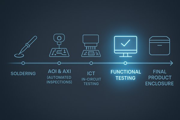
Functional testing is typically performed at the very end of the PCBA production line. It happens after all soldering and automated inspection processes (like AOI and AXI) and after In-Circuit Testing (ICT), but before the board is installed into its final product enclosure.
Positioning FCT at this stage is a strategic decision driven by the "Rule of 10s" in manufacturing cost. The rule states that the cost of fixing a defect increases by a factor of 10 for each step it moves through the production process. A fault found by FCT is far cheaper to fix than one found after final assembly or, worst of all, by a customer.
A Typical Manufacturing Test Workflow
The table below shows a simplified view of where FCT fits in, ensuring quality and controlling costs at each stage.
| Stage | Test / Process | Purpose | Typical Defects Found |
|---|---|---|---|
| 1 | SPI | Solder Paste Inspection | Insufficient/Excessive Solder Paste, Bridging |
| 2 | AOI | Automated Optical Inspection | Missing Components, Incorrect Polarity, Solder Quality |
| 3 | ICT | In-Circuit Test | Shorts, Opens, Wrong Component Values |
| 4 | FCT | Functional Test | Performance Failures, Firmware Bugs, Power Issues |
| 5 | System Test | Final Product Verification | Assembly Errors (e.g., pinched cable), User Interface Faults |
Why Is Functional Testing Necessary if Other Tests like AOI and ICT Are Performed?
You've already paid for AOI and ICT, so why add another test? It feels redundant, but skipping this step leaves a huge gap in your quality control that can lead to field failures.
Functional testing is necessary because it is the only test that verifies the board's actual behavior. AOI and ICT are structural tests; they confirm the board was built according to the blueprint. FCT is a behavioral test; it confirms the board actually performs its intended job.
I use the analogy of building a car engine. AOI is a visual check to make sure all the bolts are in place. ICT confirms every bolt is tightened to the correct torque. But neither test tells you if the engine will start. The table below summarizes the unique faults FCT can find, and the points that follow provide more detailed examples.
Defect Coverage Comparison: AOI vs. ICT vs. FCT
| Defect Type | AOI (Visual) | ICT (Structural) | FCT (Behavioral) |
|---|---|---|---|
| Incorrect Firmware | ❌ Cannot Detect | ❌ Cannot Detect | ✅ Catches (Boot Failure) |
| High Power Consumption | ❌ Cannot Detect | ❌ Cannot Detect | ✅ Catches (Measures Current) |
| Signal Integrity Issue | ❌ Cannot Detect | ❌ Cannot Detect | ✅ Catches (Bit Error Rate) |
| Marginal Component | ❌ Cannot Detect | ⚠️ May Miss | ✅ Catches (Failure under load) |
| Swapped Similar IC | ⚠️ May Miss | ⚠️ May Miss | ✅ Catches (Incorrect Function) |
Here are concrete examples of problems that only an FCT can reliably identify:
- Incorrect Crystal Frequency: ICT can confirm a 25 MHz crystal is present and soldered correctly. It cannot tell you if it's actually oscillating at 25.000 MHz. FCT, by booting the microcontroller and measuring a clock output or checking a serial port baud rate, will instantly fail if the frequency is wrong.
- Signal Integrity Issues: An improperly routed high-speed trace might pass ICT's continuity test. However, during FCT, when you're trying to transfer data at 1 Gbps, you'll see a high bit error rate that causes the test to fail.
- Power Supply Problems: ICT can verify the presence of all the components in a voltage regulator circuit. But FCT will load that regulator down and measure its output to ensure it's stable, noise-free, and within the specified voltage range (e.g., 3.3V ±3%).
- Firmware/Hardware Integration Bugs: FCT is the first time the final release firmware runs on the production hardware. It can uncover issues where the firmware tries to access a register that doesn't exist in that hardware revision or fails to correctly initialize a peripheral.
- Marginal Components: A component might be just within its tolerance and pass ICT, but when combined with other marginal components in a circuit, it can cause a functional failure at temperature or under load. FCT can expose these "tolerance stack-up" issues.
Does Functional Testing Check for Correct Component Values?
Your design calls for a 10kΩ resistor, but what if a 100kΩ resistor was placed by mistake? It's a common assembly error, but how do you catch it effectively?
Functional testing (FCT) does not directly measure component values like an ohmmeter. Instead, it indirectly verifies that the component values are correct by checking the circuit's resulting behavior. If the behavior is correct, it implies the underlying component values are also correct.
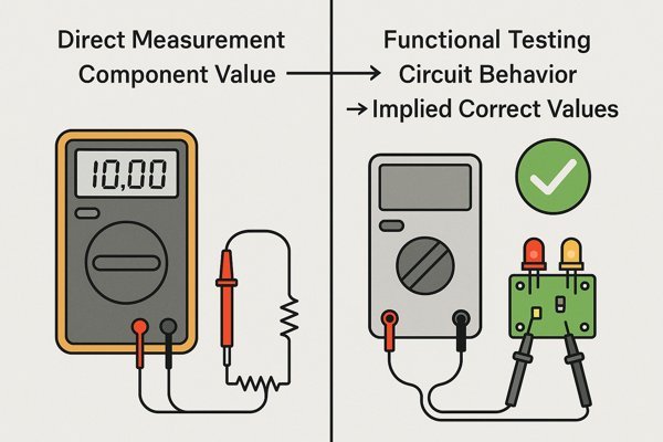
This indirect method is powerful but requires a carefully designed test. For instance, if you're testing a simple voltage divider, FCT checks if the output voltage is correct. But what if two different wrong resistor values combine to produce the correct output? It's rare, but possible. That's why a comprehensive FCT often tests a circuit under multiple conditions. For a power supply, we might test the output voltage at no-load, half-load, and full-load. This ensures the component values are correct across the operational range, not just at one lucky point.
Examples of Indirect Component Verification via FCT
- Voltage Regulator Feedback: A switching regulator uses a voltage divider to set its output voltage. If the wrong resistor value is used, the output voltage will be incorrect. FCT won't measure the resistors. Instead, it will measure the regulator's output. If the spec is 3.3V and it measures 4.1V, the board fails. The root cause is the wrong resistor, but the symptom is the incorrect voltage.
- RC Timing Circuit: A circuit uses a resistor and capacitor to set a delay. An ICT might check the R and C values individually. FCT will power the board and time the delay. If the delay is specified as 500 ms ±10%, and the test measures 5 seconds, the board fails.
- Pull-up/Pull-down Resistors: If a pull-up resistor on an I2C line is too high (100kΩ instead of 4.7kΩ), the signal's rise time will be too slow. ICT would likely pass the 100kΩ resistor. FCT, however, will try to communicate with a device on the I2C bus at 400 kHz. The communication will fail due to the slow rise time, causing the board to fail the test.
Can Functional Testing Detect Signal Integrity Issues Like Timing Errors or Noise?
Your board passes all basic checks, but it behaves erratically in the field. Intermittent crashes and data corruption often point to signal integrity problems that are notoriously hard to find.
Yes, functional testing can be very effective at detecting the symptoms of signal integrity (SI) issues, even if it doesn't directly analyze waveforms like an oscilloscope. A well-designed FCT can stress the high-speed interfaces on a board and identify failures caused by timing errors, noise, or reflections.
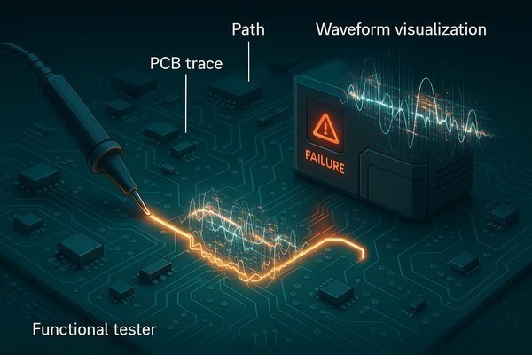
The key is that FCT is a pass/fail test based on performance. It won't show you the ringing on your clock line, but it will tell you that the DDR4 memory failed its stress test at 2400 MT/s. The SI problem is the disease, and the bit errors are the symptom that FCT detects.
Methods for Detecting Signal Integrity Faults with FCT
A robust FCT pushes the board to its specified limits:
- Bit Error Rate Testing (BERT)2: For interfaces like Ethernet or USB, the test fixture implements a loopback. The FCT commands the device to send a large stream of data (e.g., a PRBS-31 pattern, which is 2³¹-1 bits long) at maximum speed. The device reads the data back and compares it. According to standards like the Ethernet specification (IEEE 802.3), the bit error rate should be extremely low (e.g., < 10⁻¹²). FCT can send gigabits of data in seconds; even one bit error means the board fails, flagging a potential SI problem. This is a highly effective statistical method that doesn't require an expensive oscilloscope on the production line.
- Memory Stress Testing3: For systems with DDR memory, the FCT runs tests that write complex data patterns (
walking ones,march C-, etc.) to every memory address at full clock speed. This is highly effective at finding timing margin issues caused by incorrect trace lengths or poor impedance control. A single read/write error indicates a failure. - Clock Stability Verification: While FCT doesn't measure jitter directly, it can detect the effects of an unstable clock. It can program a timer to generate a 1.000 MHz signal on an output pin. A high-precision frequency counter in the test fixture measures this output. If the measurement is 998.5 kHz, it's out of spec and points to a problem with the main system clock or PLL, often rooted in layout issues or a noisy power supply.
How Does FCT Verify Power Consumption and Voltage Regulation?
Your battery-powered device is dying in hours instead of days. This common and costly problem often stems from incorrect power consumption or poor voltage regulation that basic tests completely miss.
Functional testing (FCT) uses precision measurement instruments to actively verify power consumption under different operating modes and to confirm that every voltage rail on the board is stable and within its specified tolerance. It provides a complete power profile of the board.
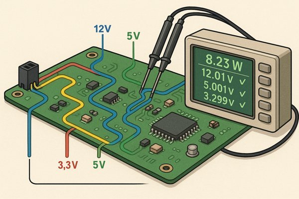
This is one of the most critical aspects of FCT, especially for IoT and portable devices. A simple solder bridge can cause a subsystem to stay powered on, increasing sleep current from 10 microamps to 5 milliamps—a 500x increase that would kill battery life. For accurate measurements, the test fixture must be designed properly. For example, when measuring a high-current rail, we use 4-wire (Kelvin) connections4 to eliminate voltage drop across the test probes and cables, ensuring the DMM measures the voltage at the PCBA, not at the test fixture.
Example Power Verification Tests During FCT
| Test Parameter | Operating Mode | Example Specification | Why It Matters |
|---|---|---|---|
| Sleep Current | Deep Sleep | < 10 µA | Determines battery life in standby. |
| Active Current | Transmitting Data | 150 mA ± 20% | Ensures the power supply can handle peak loads. |
| 3.3V Rail Accuracy | Full Load | 3.3V ± 3% (3.20V - 3.40V) | Prevents damage or malfunction of sensitive ICs. |
| Voltage Ripple | Full Load | < 50 mVp-p | Ensures clean power for analog and high-speed digital circuits. |
Can Functional Testing Identify Firmware or Software-Related Bugs?
The hardware seems perfect, but the product still doesn't work. Often, the problem lies in the interaction between the firmware and the hardware, an area where other tests are blind.
Yes, functional testing is one of the most effective ways to identify firmware and software-related bugs on production hardware. It is often the very first time that the final, release-candidate firmware is run on a mass-produced PCBA, making it a critical step for validation.
I've personally seen FCT catch everything from incorrect bootloader configurations to peripheral drivers written for a different hardware revision. These are design and software integration issues that only become apparent when you operate the board as a system. For instance, FCT can catch issues with non-volatile memory5. A test might include a step to explicitly erase an on-board EEPROM or flash chip to ensure a consistent starting state. I've seen boards fail because leftover data from a previous debug session caused the firmware to boot into an unexpected factory test mode.
How FCT Finds Firmware Flaws
The FCT process exercises the firmware in a controlled, automated way:
- Programming the Device: The test fixture uses a programming probe (e.g., JTAG or SWD) to flash the production firmware. If the device can't be programmed, it's an immediate failure.
- Verifying the Boot Process: The board is power-cycled. The FCT controller monitors a UART for specific boot-up messages. A common technique is to have the firmware print a string like "Boot Successful v1.2.3" once initialization is complete. This not only confirms the boot but also verifies the correct firmware version.
- Executing Specific Functions: The firmware's "test mode" is activated. The FCT controller sends commands to instruct the firmware to perform actions:
"SET_LED_RED""READ_TEMP_SENSOR""TOGGLE_RELAY_3"
- Verifying the Outcome: The FCT fixture uses its own hardware to verify the outcome. After sending
"SET_LED_RED", a light sensor checks that the LED is on and that its color is red. After"READ_TEMP_SENSOR", it compares the returned temperature value to a known ambient sensor in the fixture. This closed-loop system provides definitive proof that the firmware is correctly controlling the hardware peripherals.
What Types of Assembly Errors Can Only Be Found with Functional Testing?
Your boards are passing both visual inspection (AOI) and electrical checks (ICT), yet some still fail in the field. This frustrating situation often points to subtle assembly errors that these earlier tests can't detect.
Functional testing is uniquely capable of finding assembly errors where the board is built "correctly" from a structural standpoint but is "incorrectly" from a functional one. These include swapped but similar-looking components, reversed polarity on parts that don't cause a short, and marginal cold solder joints.
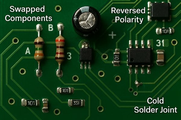
In my career, I've seen some baffling failures that were ultimately traced back to these kinds of sneaky assembly defects. The table below summarizes these errors, and the descriptions that follow provide more detail.
Common Assembly Errors Missed by AOI and ICT
| Error Type | Description | Why AOI/ICT Misses It | How FCT Catches It |
|---|---|---|---|
| Swapped Similar Components | A 0.1µF capacitor is used instead of a 1.0µF capacitor (same package). | AOI sees the correct package. ICT may pass if tolerance is wide. | The circuit (e.g., a filter or timer) behaves incorrectly. |
| Counterfeit IC | A fake IC with correct markings is used. | AOI sees correct markings. ICT may see basic I/O signature correctly. | The IC fails performance-based commands or complex operations. |
| Cold Solder Joint | A solder joint makes a weak, high-resistance connection. | AOI may not see it. ICT passes a low-voltage continuity test. | The connection fails under thermal stress or operational current. |
| Reversed LED | An LED is soldered with anode and cathode swapped. | AOI may miss subtle polarity marks. ICT sees it as a diode, passing continuity. | The FCT test to turn on the LED fails; no light is detected. |
These errors highlight why FCT is not just a redundant check but a vital, distinct step in ensuring product quality. An AOI can't tell the difference between a 1.0µF capacitor and a 0.1µF capacitor in the same 0402 package. An ICT might not catch it. But a functional test, which relies on that capacitor for proper circuit operation, will fail the board immediately.
Conclusion
Functional testing is the ultimate quality check, ensuring your PCBA works as designed in the real world. It catches critical functional, firmware, and performance-related flaws that other tests simply cannot.
-
Understanding DFT is essential for improving test efficiency and product reliability in electronics. ↩
-
Explore this link to understand BERT's role in ensuring data integrity in high-speed interfaces like Ethernet and USB. ↩
-
Learn about Memory Stress Testing to see how it identifies timing margin issues in DDR memory systems effectively. ↩
-
Exploring 4-wire connections reveals how they eliminate voltage drop, leading to precise measurements essential for device performance. ↩
-
Understanding non-volatile memory is crucial for grasping how firmware interacts with hardware, ensuring reliable system performance. ↩


