 Skip to content
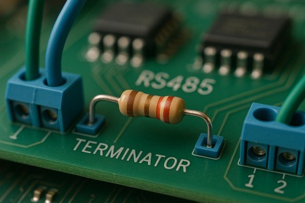
Your RS485 network is failing with random, frustrating errors. You've checked the code and the transceivers, but the problem persists. The real culprit might be a tiny, overlooked component.
A termination resistor is crucial in RS485 networks to prevent destructive signal reflections. It matches the cable's characteristic impedance, absorbing signal energy at the end of the bus. This ensures clean signal integrity and reliable communication, especially at high data rates or over long distances.
Understanding why we need termination is the first step. But as engineers, we know the details are what separate a working prototype from a reliable product. A robust design requires getting the value, placement, and implementation exactly right. Let's dig into the specifics of making your RS485 network bulletproof.
What Value Should the RS485 Termination Resistor Be?
You're trying to select the right termination resistor for your RS485 bus. Choosing the wrong value can introduce subtle signal integrity problems that are a nightmare to debug later on.
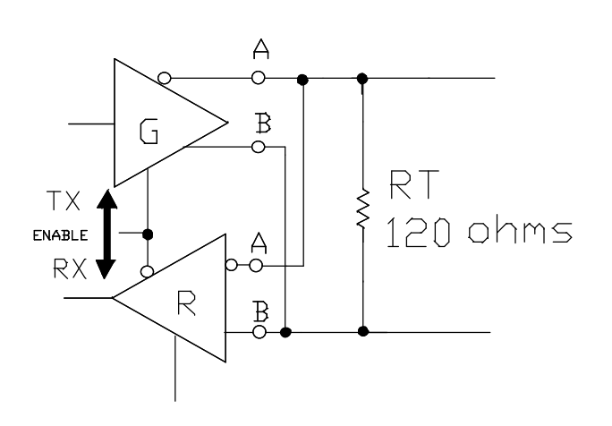
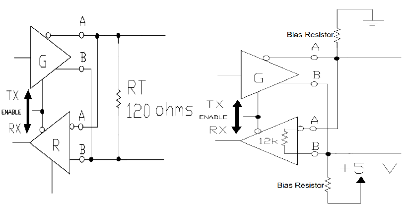
The standard value for an RS485 termination resistor is 120\(\Omega\). This value is specifically chosen to match the characteristic impedance (\(Z_{0}\)) of the twisted-pair cable defined in the TIA/EIA-485-A standard. Using a 120\(\Omega\) resistor makes the cable appear electrically "infinite" to the signal.
Matching the Cable's Characteristic Impedance
The goal of termination is impedance matching. The characteristic impedance1 (\(Z_{0}\)) is an AC impedance determined by the cable's physical construction—specifically its distributed inductance (\(L\)) and capacitance (\(C\)) per unit length. For standard RS485 twisted-pair, this value is 120\(\Omega\).
| Cable Type | Typical Characteristic Impedance (\(Z_{0}\)) | Recommended Termination |
|---|---|---|
| Standard RS485 Twisted Pair | 120\(\Omega\) | 120\(\Omega\) |
| Cat5/Cat5e/Cat6 UTP | 100\(\Omega\) | 100\(\Omega\) |
Power Rating Considerations
A final detail is the resistor's power rating. Current flows through the terminators when the bus is active. You must select a resistor that can handle the worst-case power dissipation.
| Max Driver Voltage | Resistor Value | Power Dissipation (\(P = \frac{V^2}{R}\)) | Recommended Rating |
|---|---|---|---|
| 3.3V | 120\(\Omega\) | \(\frac{(3.3\text{V})^2}{120\Omega} = 91\text{mW}\) | 1/8W (125mW) or higher |
| 5.0V | 120\(\Omega\) | \(\frac{(5.0\text{V})^2}{120\Omega} = 208\text{mW}\) | 1/2W (500mW) |
As you can see, a standard 1/4W (250mW) resistor is marginal for a 5V system. I recommend using a 1/2W resistor to ensure a safe operating margin.
Where are Termination Resistors Placed in an RS485 Network?
You know you need termination resistors, but you're not sure about the exact placement. Putting them in the wrong spot can be just as bad as not using them at all.
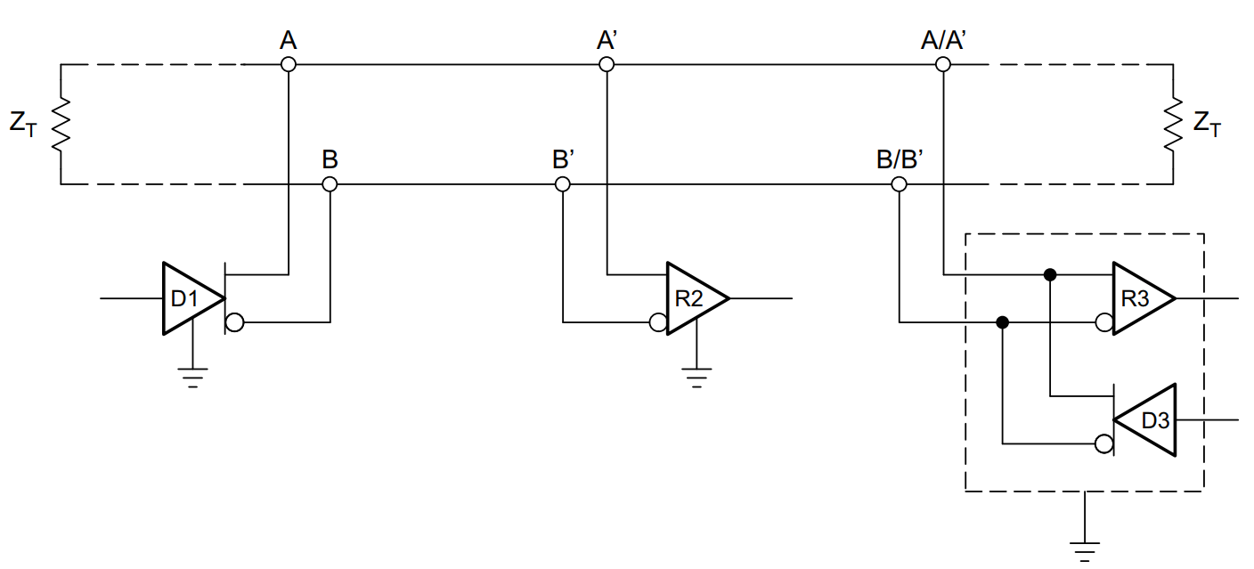
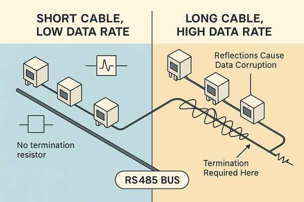
Termination resistors must be placed only at the two physical ends of the main bus trunk. They should never be placed at intermediate nodes or on unterminated stubs. This ensures that reflections from both ends of the primary signal path are absorbed correctly.
What Defines the "End of the Bus"?
The "end" refers to the two devices at the physical extremes of the main cable trunk. It is not about the logical address of the device (e.g., node #1 or node #32). You must trace the actual path of the wire. The two devices that are furthest apart on that wire are the ones that get the termination resistors.
The Problem with Stubs
A "stub" is a short branch off the main bus that connects to a device. The TIA/EIA-485-A standard2 advises keeping stubs as short as possible because they create their own reflections. Terminating a stub is a serious error because it adds a third parallel resistor to the bus, which can overload the driver.
What Happens if a Termination Resistor is Not Used in RS485?
You might be tempted to leave out the termination resistor to save a few cents or simplify the board. This small saving can lead to hours of frustrating debugging down the line.
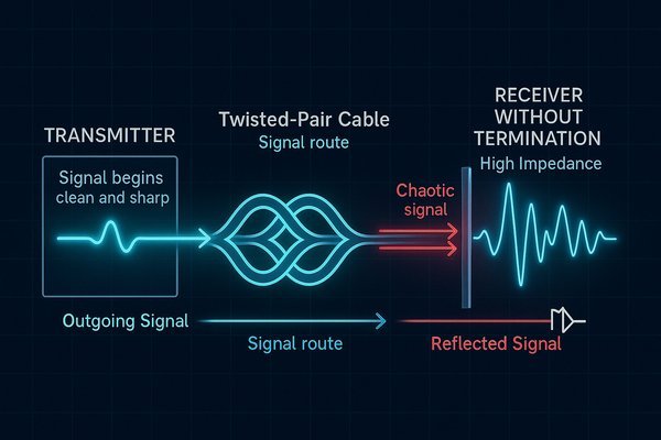
Without a termination resistor, the signal hits the high-impedance receiver at the end of the line and reflects back, like an echo. This reflection corrupts the original signal, causing severe overshoot, ringing, and potential bit errors, which makes communication unreliable.
Diagnostic Guide
If your network is unreliable, you can often diagnose the issue by observing the symptoms. This table provides a quick guide.
| Symptom | Likely Cause | Oscilloscope Observation |
|---|---|---|
| High bit error rate, especially at high speed | Missing termination resistor(s) | Severe overshoot and ringing on signal edges |
| Communication fails completely | Driver overload | Signal voltage is too low to meet receiver thresholds |
| Intermittent errors, random node dropouts | Incorrect terminator placement (e.g., on stubs) | Distorted waveforms, inconsistent signal levels |
When is it Okay Not to Use a Termination Resistor in RS485?
You've seen how critical termination is, but are there ever exceptions? It seems like an absolute rule, but in some specific, limited cases, you might get away without it.
You can often omit termination resistors when the network meets two conditions simultaneously: a very low data rate and a very short cable run. In this scenario, reflections settle down before the next bit is sampled.
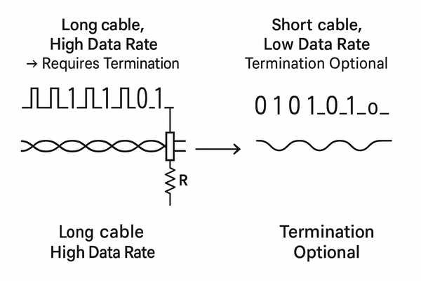
The "Electrically Short" Line
The key factor is the relationship between the signal's rise time and the cable's propagation delay3. A transmission line is "short" if its round-trip propagation delay is much less than the signal's rise/fall time. If the reflection returns and settles before the receiver samples the bit, it doesn't cause an error.
Termination Decision Guide
This table gives a practical rule of thumb. If you fall into the "Required" or "Recommended" category, include termination.
| Data Rate | Cable Length < 10m | Cable Length 10m - 50m | Cable Length > 50m |
|---|---|---|---|
| < 100 kbps | Optional | Recommended | Required |
| 100 kbps - 1 Mbps | Recommended | Required | Required |
| > 1 Mbps | Required | Required | Required |
My professional recommendation is to always include the resistor footprint on your PCB. It costs nothing and saves you from future headaches.
How Does Cable Length and Data Rate Affect the Need for RS485 Termination?
You understand the basics, but how do you know when you've crossed the line from a "short" network to one that absolutely requires termination? The answer lies in the interplay between speed and distance.
The need for termination becomes critical as cable length increases or data rate increases. A longer cable means a longer delay for reflections to return, and a higher data rate means less time for them to settle before the next bit arrives.
The Inverse Relationship
The TIA/EIA-485-A standard defines a clear trade-off between how fast you can send data and how far you can send it. As one goes up, the other must come down.
| Data Rate | Maximum Cable Length |
|---|---|
| 100 kbps | 1200 m (4000 ft) |
| 1 Mbps | 120 m (400 ft) |
| 10 Mbps | 12 m (40 ft) |
Don't Forget Cable Quality
This relationship assumes you are using high-quality, low-capacitance cable designed for RS485. Using a cheaper, high-capacitance cable will attenuate the high-frequency components of your signal, reducing the maximum usable cable length at any given data rate, even with perfect termination.
What is the Difference Between Termination and Biasing Resistors in RS485?
You may hear "termination" and "biasing" discussed together, and it's easy to get them confused. While both use resistors to improve reliability, they solve two completely different problems on the RS485 bus.
Termination resistors prevent signal reflections at the physical ends of the bus. Biasing resistors, on the other hand, ensure the bus maintains a valid logic state when no devices are transmitting (i.e., when the bus is idle).
What "Fail-Safe" Really Means
Fail-safe biasing protects against several conditions: idle bus, open-circuit, and short-circuit. External biasing is the most robust way to guarantee a known state for the entire network.
| Feature | Termination | Fail-Safe Biasing |
|---|---|---|
| Problem Solved | AC signal reflection | DC idle state ambiguity |
| Location | Two ends of the bus | Typically one location |
| Components | Single 120\(\Omega\) resistor | Pull-up and pull-down resistors |
How to Add Fail-Safe Biasing to an RS485 Network?
You know you need to prevent the idle bus state from causing errors, but how do you implement fail-safe biasing correctly? The solution involves a pull-up and a pull-down resistor.
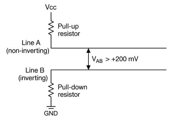
To add fail-safe biasing, you use a pull-up resistor on the A line (non-inverting) and a pull-down resistor on the B line (inverting). These resistors ensure a small positive differential voltage (\(V_{AB} > +200 \text{ mV}\)) when no driver is active.
Example Biasing Values
The biasing resistors (\(R_{B}\)) form a voltage divider with the bus's total termination resistance (\(R_{T_{eq}} = 60\Omega\)). The goal is to select an \(R_{B}\) that provides a sufficient idle voltage without drawing too much power. Here are some practical examples:
| System Voltage (\(V_{CC}\)) | Biasing Resistors (\(R_{B}\)) | Idle Bus Voltage (\(V_{AB}\)) |
|---|---|---|
| 3.3V | 560\(\Omega\) | \(\approx 170 \text{ mV}\) (Marginal) |
| 3.3V | 470\(\Omega\) | \(\approx 200 \text{ mV}\) (Meets minimum) |
| 5.0V | 620\(\Omega\) | \(\approx 230 \text{ mV}\) (Good) |
| 5.0V | 560\(\Omega\) | \(\approx 255 \text{ mV}\) (Good) |
External vs. Integrated Fail-Safe
Many modern transceivers have built-in fail-safe features. While useful, this only protects the local receiver. External biasing, in contrast, forces the entire bus into a known idle state, providing a more robust solution for the whole network.
Can More Than Two Termination Resistors Be Used on an RS485 Bus?
You have a complex network layout, perhaps with multiple branches, and you're wondering if you can just add terminators at the end of each branch to keep the signals clean.
No, you should never use more than two termination resistors on a single RS485 bus segment. The bus is designed as a single transmission line with two ends, and only those two ends should be terminated.
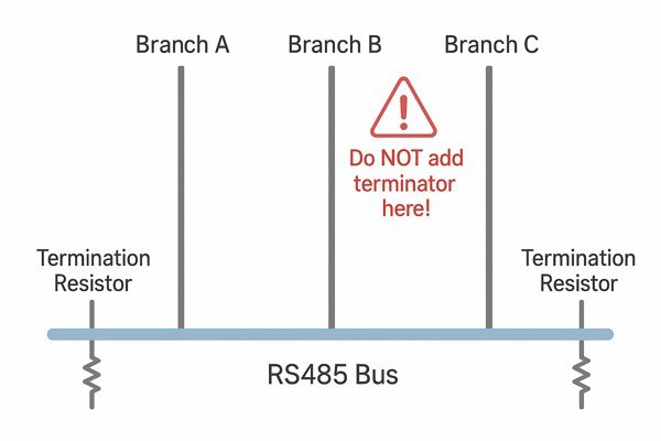
Adding a third 120\(\Omega\) resistor drops the total equivalent resistance from 60\(\Omega\) to 40\(\Omega\). This overloads the driver, causing the signal voltage to collapse. If your network topology has a "star" configuration, the correct solution is to use RS485 repeaters to create separate, properly terminated bus segments.
How to Test for Proper RS485 Network Termination?
Your network is built, but you're seeing intermittent issues. How can you definitively test whether the termination is implemented correctly and is effective? There are two simple and reliable methods.
You can test for proper termination both offline with a multimeter and online with an oscilloscope. A multimeter check gives a quick sanity check, while an oscilloscope provides a complete picture of the signal integrity on the live bus.
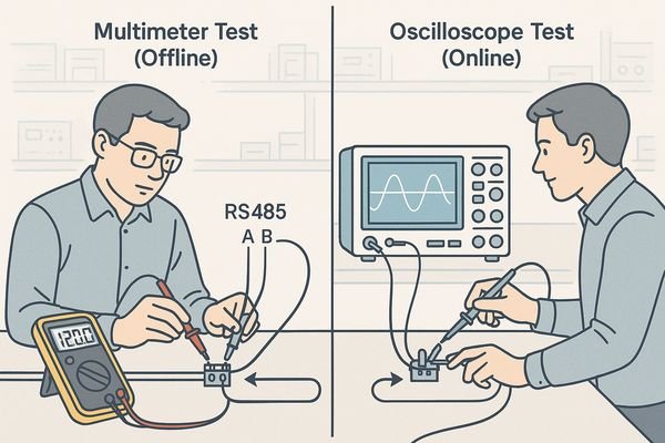
Method 1: The Multimeter Test (Power Off)
This is the fastest way to confirm the physical presence of the termination resistors. Power down the network and measure the resistance between the A and B terminals.
| Measured Resistance | Inferred State of Termination |
|---|---|
| \(\approx 60\Omega\) | ✅ Correct (Two 120\(\Omega\) terminators are present) |
| \(\approx 120\Omega\) | ❌ Incorrect (One terminator is missing) |
| High (k\(\Omega\) or M\(\Omega\)) | ❌ Incorrect (Both terminators are missing) |
Method 2: The Oscilloscope Test (Power On)
This is the definitive test for signal quality. Use the scope's math function to display the differential signal (A - B). You're looking for clean, square-like waves. The ringing after a transition should be minimal and must not cross the receiver's input threshold during the time the bit is being sampled.
Advanced Method: Time-Domain Reflectometry4 (TDR)
For critical systems, a TDR is the ultimate tool. It sends a pulse down the cable and measures reflections, creating a map of impedance vs. distance. This allows you to "see" the entire bus and pinpoint the exact location of a missing terminator or a bad connection.
Conclusion
Proper RS485 termination isn't just a recommendation; it's a fundamental requirement for a reliable network. By using a 120\(\Omega\) resistor at each of the two bus ends, you ensure signal integrity and prevent frustrating, hard-to-diagnose communication failures.
-
Understanding characteristic impedance is crucial for effective impedance matching in cable systems. ↩
-
Exploring this standard will provide insights into best practices for network design and performance. ↩
-
Understanding propagation delay is crucial for optimizing signal integrity in your designs. ↩
-
Time-Domain Reflectometry is essential for diagnosing cable issues. Discover its applications and benefits through this resource. ↩


